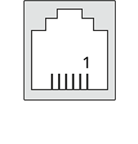
| X10 RS485 Connector | |||
| Appearance | Pin | Name | Description |
|---|---|---|---|
| 1 | B- | RS485 Negative signal |
| 2 | A+ | RS485 Positive signal | |
| 3 |
| RS485 SHIELD (ISOGND) | |
SolarGatewaySE User Manual
Copyright Embion BV. All rights reserved.
No part of this document may be reproduced, stored in a retrieval system, or transmitted in any form or by any means, electronic, mechanical, photocopying, recording, or otherwise, without the prior written permission of Embion B.V. The information contained in this document is subject to change without notice. Embion B.V. makes no warranty of any kind with respect to this information, including but not limited to the implied warranties of merchantability and fitness for a particular purpose. Embion B.V. shall not be liable for errors contained herein or for incidental or consequential damages in connection with the furnishing, performance, or use of this material.
Disclaimer
The SolarGatewaySE is designed for use in electrical systems, but it is not a safety device. It is the responsibility of the user to ensure that the system is properly equipped with the necessary safety measures to protect against any potential hazards. If the user is unsure about the safety requirements of their electrical system, they should consult with a qualified installer or distributor to determine what additional components or redundancy measures may be necessary. Embion B.V. cannot be held liable for any damages or injuries resulting from the use of the SolarGatewaySE without proper safety measures in place. By using this product, the user acknowledges and accepts this disclaimer.
Warranty for the SolarGatewaySE
Embion B.V. provides a limited warranty for the SolarGatewaySE (the “Product”) to the original purchaser (“Purchaser”) for a period of two (2) years from the date of purchase.
Embion B.V. warrants that the Product will be free from defects in materials and workmanship under normal use and service. If any defects in the Product occur during the warranty period, Embion B.V. will, at its sole option and cost, either repair or replace the defective Product or refund the purchase price paid by the Purchaser.
This warranty does not cover any damage caused by misuse, abuse, accident, neglect, or unauthorized modification of the Product. The warranty also does not cover any damage caused by natural disasters.
To make a warranty claim, the Purchaser must provide proof of purchase and contact the reseller of the SolarGatewaySE. The reseller will provide instructions on how to return the defective Product and receive a replacement or refund.
THIS WARRANTY IS THE ONLY EXPRESS WARRANTY MADE BY EMBION B.V. WITH RESPECT TO THE PRODUCT. EMBION B.V. EXPRESSLY DISCLAIMS ALL OTHER WARRANTIES, INCLUDING BUT NOT LIMITED TO IMPLIED WARRANTIES OF MERCHANTABILITY AND FITNESS FOR A PARTICULAR PURPOSE. IN NO EVENT SHALL EMBION B.V. BE LIABLE FOR ANY INCIDENTAL, SPECIAL, OR CONSEQUENTIAL DAMAGES ARISING OUT OF OR IN CONNECTION WITH THE PRODUCT OR THIS WARRANTY.
Some jurisdictions do not allow limitations on how long an implied warranty lasts or the exclusion or limitation of incidental or consequential damages, so the above limitations may not apply to the Purchaser. This warranty gives the Purchaser specific legal rights, and the Purchaser may also have other rights which vary from jurisdiction to jurisdiction.
This warranty is governed by and shall be construed in accordance with the laws of the Netherlands without giving effect to any choice of law or conflict of law provisions. Any dispute arising out of or in connection with this warranty shall be resolved by the courts of the Netherlands.
About this document
Purpose
This document introduces the SolarGatewaySE (GSE) in terms of installation, electrical connections, system operation and maintenance and troubleshooting. Understand the SolarGatewaySE features, functions and safety precautions provided in this document before installing and operating the SolarGatewaySE.
To ensure an identical menu layout, please make sure that the version number of this document corresponds to the software release of the SolarGatewaySE.
Intended Audience
This document is intended for operating personnel, system engineers adopting the SolarGatewaySE in there system design.
Symbol coventions
The symbols that may be found in this document are defined as follows:
Note
Used for general notes in this documentation
Warning
Used for expressing warnings in this documentation
Important
Used for important notes in this documentation
Tip
Used for general tips in this documentation
Caution
Used for caution notes in this documentation
Change history
V2.6.1 - Fix EV charge control without inverters, Fix Eastron power factor readout. 10/27/2023
V2.6.0 - Add support for Altilia, Eaton Xstorage, Deye and Sofar G3 Hybrid inverters and Chint DTSU666 energy meter. Fix TCP IP configuration. 09/29/2023
V2.5.0 - Add ABB PVS inverter. Bugfix for GPO configuration in general template. 09/20/2023
V2.4.0 - New limits for countering strategy. Allow prio select for controlled loads. Enable data compression on the portal connection to significantly reduce the required internet data. Minor changes and bug fixes. 09/11/2023
V2.3.0 - Add “low power limit” control for generic strategy. Improve Countering strategy with requirements Enexis. Add support for EV chargers. Minor changes. 08/15/2023
V2.2.1 - Add gridvoltage control, active power control and GPIO control. Update supported inverter list and ETH0 and ETH1 settings. Minor changes. 07/21/2023
V2.1.0 - Update disclaimer, add IP range configuration for inverter, meter EV charger and auxiliaries, add split solar and grid option for load meters, add MLOEA configuration for grid meter and add system language configuration. Added warenty information. 04/11/2023
V2.0.0 - First release of the user manual 03/10/2023
Safety information
General Safety
Statement
Before installing, operating or maintaining the equipment, read this document and observe all safety instructions on the equipment and in this document.
The “Warning”, and “Caution” statements in this document do not cover all the safety instructions. They are only supplements to the safety instructions. Embion will not be liable for any consequence caused by the violation of general safety requirements.
Ensure that the equipment is used in environments that meet its design specifications. Otherwise, the equipment may become faulty, the resulting equipment malfunction, component damage, personal injuries, or property damage are not covered under the product warranty.
Follow local laws and regulations when installing, operating, or maintaining the equipment. The safety instructions in this document are only supplements to local laws and regulations.
Embion will not be liable for any consequences of the following circumstances:
Operation beyond the conditions specified in this document
Installation or use in environments which are not specified in relevant international or national standards
Unauthorized modifications to the product, software or removal of the product warranty sticker
Failure to follow the operation instructions and safety precautions on the product and in this document
Equipment damage due to force majeure, such as earthquakes, fire, and storms
Damage caused during transportation by the customer
Storage conditions that do not meet the requirements specified in this document
General requirements
Warning
Do not work with system power turned-on during installation
After installing the equipment, remove idle packing materials such as cartons, foam, plastics, and cable ties from the equipment area
In the case of a fire, immediately leave the building or the equipment area, and turn on the fire alarm bell or make an emergency call. Do not enter the building on fire in any case
Do not scrawl, damage, or block any warning label on the equipment
Tighten the screws using the correct tools when installing the equipment
Understand the components and functioning of the system, the SolargatewaySE and relevant local standards
You shall not to reverse engineer, decompile, disassemble, adapt, add code to, or alter in any other way, the device software; research the internal implementation of the device; obtain the device software source code; infringe on Embion’s intellectual property; or disclose any performance test results related to the device software.
Personal safety
If there is a probability of personal injury or equipment damage during operations on the equipment, immediately stop the operations, report the case to the supervisor, and take feasible protective measures.
Use tools correctly to avoid hurting people or damaging the equipment
Personnel requirements
Personnel who plan to install or maintain Embion equipment must receive thorough training, understand all necessary safety precautions, and be able to correctly perform all operations
Only qualified professionals or trained personnel are allowed to install, operate, and maintain the equipment
Only qualified professionals are allowed to remove or acknowledge any safety lock or notification on the device
Only professionals or authorized personnel are allowed to replace the equipment or components
Note
Professionals: personnel who are trained or experienced in equipment operations and are clear of the sources and degree of various potential hazards in equipment installation, operation, and maintenance. It is task of a professional to understand the working concept of the complete system. This is required to correctly configure the SolargatewaySE
Trained personnel: personnel who are technically trained, have required experience, are aware of possible hazards on themselves in certain operations, and are able to take protective measures to minimize the hazards on themselves and other people
Operators: operation personnel who may come in contact with the equipment, except trained personnel and professionals
Electrical Safety
General
Warning
Before connecting cables, ensure that the equipment is intact. Otherwise, electric shocks or fire may occur.
Ensure that all electrical connections comply with local electrical standards.
Ensure that the cables you prepared meet local regulations.
Product power supply
Warning
Do not connect or disconnect power cables with power on.
Before making electrical connections, switch off the disconnector on the upstream,
Before connecting a power cable, check that the label on the power cable is correct.
If the equipment has multiple energized inputs, disconnect all the energized inputs before operating the equipment.
Installation environment requirements
Ensure that the equipment is installed in a well ventilated environment.
Ensure the enviroment temperature does not exceed the maximum allowed environment temperature.
Do not expose the equipment to flammable or explosive gas or smoke. Do not perform any operation on the equipment in such environments.
Commussioning
When the equipment is powered on for the first time, ensure that professional personnel set parameters correctly. Incorrect settings may result in damage to subsystems connected to the SolargatewaySE.
Maintenance and replacement
Maintain the equipment with sufficient knowledge of this document and using proper tools and testing equipment.
If the equipment is faulty, contact your dealer.
The equipment can be powered on only after all faults are rectified. Failing to do so may escalate faults or damage the equipment.
Product overview
Model description
This document covers the following SolarGatewaySE models:
GSE-A010
GSE-A010-POE
Model identification
The model number of the SolarGatewaySE can be found on the label on the side of the device. The model number is listed on the label under PN (Product Name).
Label appearance
![]()
Serial Number
MAC Addresses
Product Name
PIN Code
Datamatrix
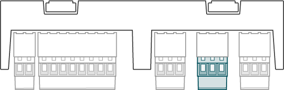
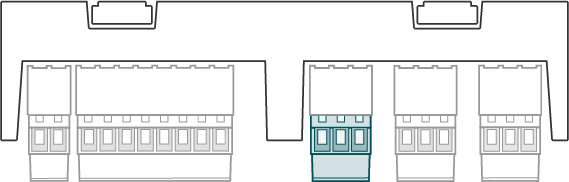
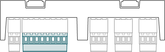
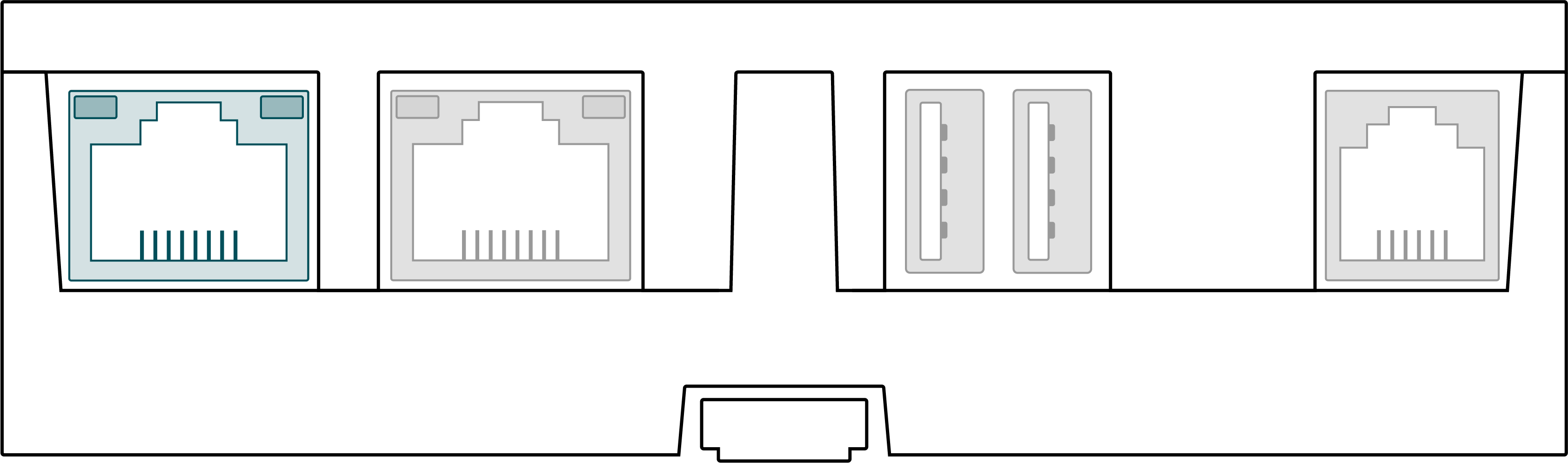
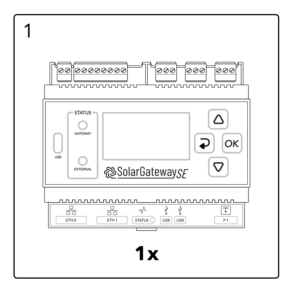
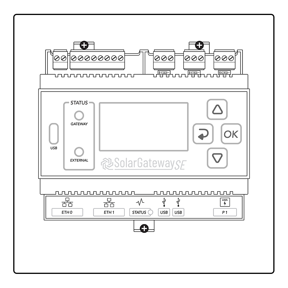
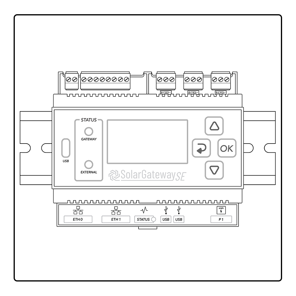
Product appearance
![]()
X14 DC Input Port
X13 GPIO Port
X12 RS485 Port C
X11 RS485 Port B
X10 RS485 Port A
ETH Port 0 / POE
ETH Port 1
Status LED
USB Port 0
USB Port 1
P1 Port
LCD Screen
Gateway status LED
USB-C Port
Service status LED
X10 termination switch
X11 termination switch
X12 termination switch
Arrow up button
Back button
OK button
Arrow down button
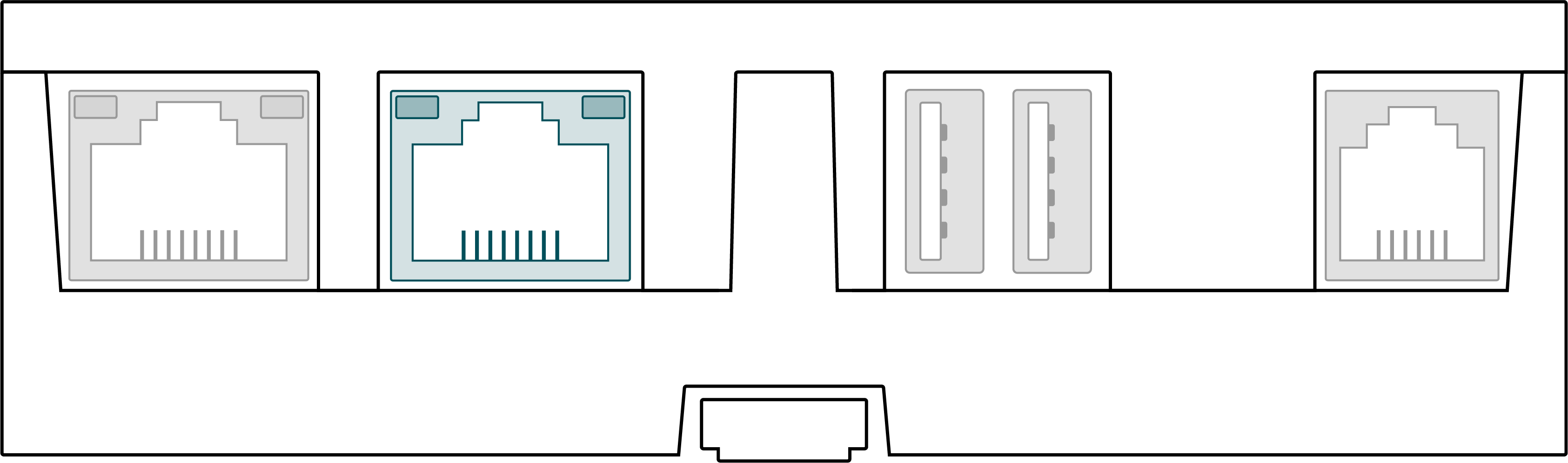
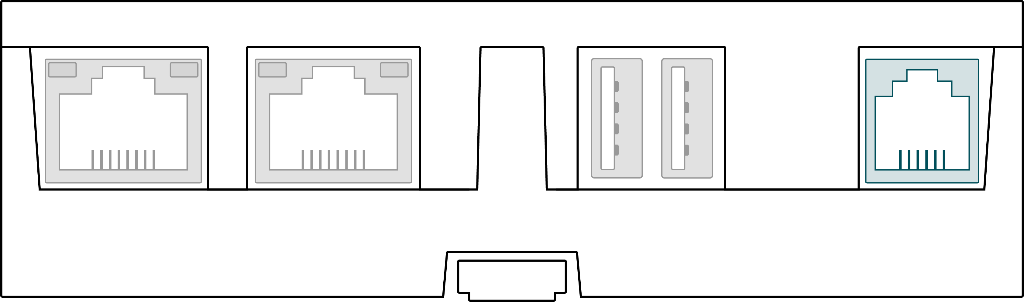
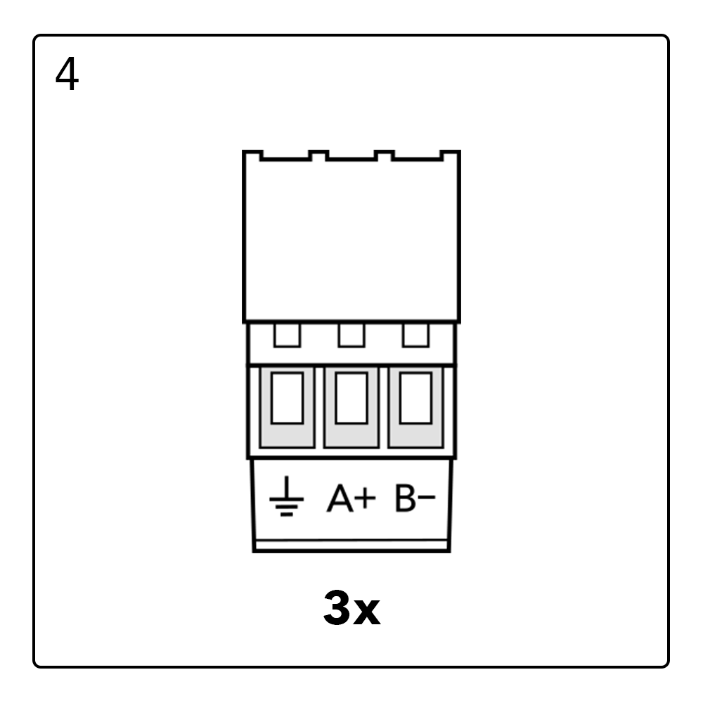
Communication ports
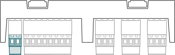
X10 RS485 Default inverter port
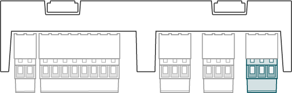
The X10 RS485 connector is the default inverter port. It is possible to deviate from the default and use the port for something else as inverters.

| X10 120 ohm termination switch | |
| Position | Description |
|---|---|
| Termination ON |
| Termination OFF |


The X10 120 ohm termination switch is used to terminate the the X10 RS485 bus.
Important
The protocol and port settings (baudrate, parity databits and stopbits) need to be identical for all devices connected to the X10 port. Every (Modbus) slave address should be unique per port.
X11 RS485 Default meter port
The X11 RS485 connector is the default meter port. It is possible to deviate from the default and use the port for something else as meters.
| X11 RS485 Connector | |||
| Appearance | Pin | Name | Description |
|---|---|---|---|
| 1 | B- | RS485 Negative signal |
| 2 | A+ | RS485 Positive signal | |
| 3 |
| RS485 SHIELD (ISOGND) | |
| X11 120 ohm termination switch | |
| Position | Description |
|---|---|
| Termination ON |
| Termination OFF |
The X11 120 ohm termination switch is used to terminate the the X11 port.
Important
The protocol and port settings (baudrate, parity databits and stopbits) need to be identical for all devices connected to the X11 port. Every (Modbus) slave address should be unique per port.
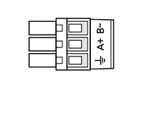
X12 RS485 Default Auxiliaries port
The X12 RS485 connector is the default auxiliary devices port. It is possible to deviate from the default and use the port for something else as auxiliary devices.
| X12 RS485 Connector | |||
| Appearance | Pin | Name | Description |
|---|---|---|---|
| 1 | B- | RS485 Negative signal |
| 2 | A+ | RS485 Positive signal | |
| 3 |
| RS485 SHIELD (ISOGND) | |
| X12 120 ohm termination switch | |
| Position | Description |
|---|---|
| Termination ON |
| Termination OFF |
The X12 120 ohm termination switch is used to terminate the the X12 port.
Important
The protocol and port settings (baudrate, parity databits and stopbits) need to be identical for all devices connected to the X12 port. Every (Modbus) slave address should be unique per port.
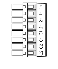
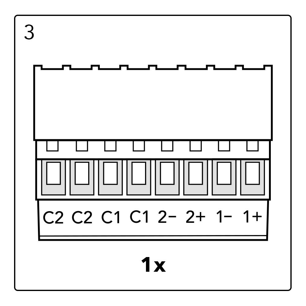
X13 GPIO Port
The X13 GPIO connector can be used for genral input/output control.
| X13 GPIO Port | |||
| Appearance | Pin | Name | Description |
|---|---|---|---|
| 1 | 1+ | Potential free input #1 (+) |
| 2 | 1- | Potential free input #1 (-) | |
| 3 | 2+ | Potential free input #2 (+) | |
| 4 | 2- | Potential free input #2 (-) | |
| 5 | C1 | Potential free output contact #1 | |
| 6 | C1 | Potential free output contact #1 | |
| 7 | C2 | Potential free output contact #2 | |
| 8 | C2 | Potential free output contact #2 | |
| GPIO electrical specifications | |||
| Item | Min | Max | Unit |
|---|---|---|---|
| Input 'low' voltage | -32.0 | 2.0 | V |
| Input 'high' voltage | 5.0 | 32.0 | V |
| Input forward current | 1.0 | 6.0 | mA |
| Contact (C) switch voltage | - | 32.0 | V |
| Contact (C) switch current | - | 2.0 | A |
| GPIO isolation voltage | - | 48.0 | V |
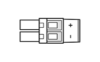
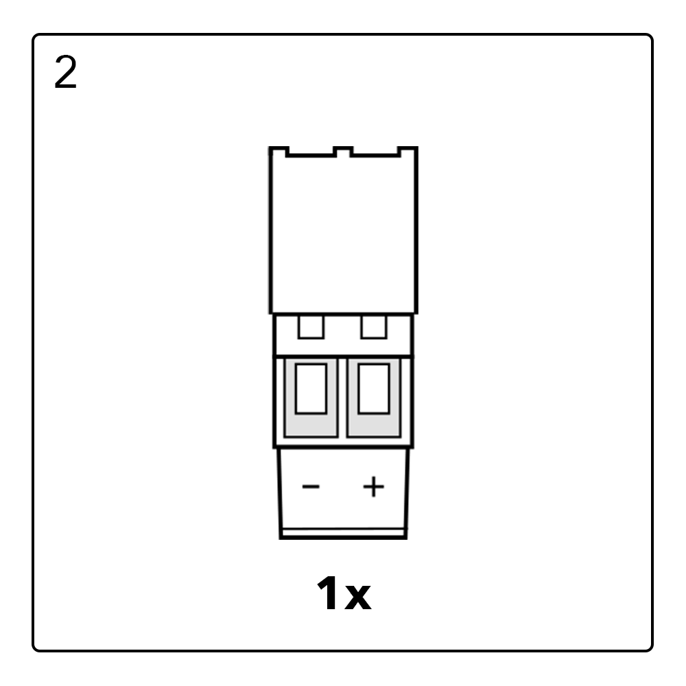
X14 DC Input Port
| X14 DC Port | |||
| Appearance | Pin | Name | Description |
|---|---|---|---|
| 1 | + | External DC power supply (+) |
| 2 | - | External DC power supply (-) | |
| DC input supply specifications | |||
| Item | Min | Max | Unit |
|---|---|---|---|
| DC input voltage | 12.0 | 32.0 | V |
| DC input current | - | 2.0 | A |
| DC input power | - | 20.0 | W |
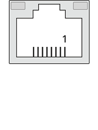
ETH0 Port / POE
The ETH0 port can be used as normal Ethernet port and for powering the SolarGatewaySE with Power over Ethernet (POE) (only for the POE variants).
Port specifications
- 10/100/1000 Mbps
For the POE variant (PN: GSE-A010-POE):
- IEEE 802.3af PoE support (not recommended due to the power limit), device may reduce performance
- IEEE 802.3at PoE+ support
- Redundant power source possible, autmatically switches between PoE and DC input. If both are present, PoE is prefferred.
| ETH0 Pinning | ||
| Appearance | Pin | Description |
|---|---|---|
| 1 | BI_DA+ |
| 2 | BI_DA- | |
| 3 | BI_DB+ | |
| 4 | BI_DC+ | |
| 5 | BI_DC- | |
| 6 | BI_DB- | |
| 7 | BI_DD+ | |
| 8 | BI_DD- | |
| ETH0 Indicators | |
| Indicator | Description |
|---|---|
| Green | Blinks when data is transmitted/received |
| Yellow | On when POE+ source is connected |
ETH1 Port
The ETH1 port can be used for ethernet connections on the SolarGatewaySE
Port specifications
- 10/100 Mbps
| ETH1 Pinning | ||
| Appearance | Pin | Description |
|---|---|---|
| 1 | TX+ |
| 2 | TX- | |
| 3 | RX+ | |
| 4 | NC | |
| 5 | NC | |
| 6 | RX- | |
| 7 | NC | |
| 8 | NC | |
| ETH1 Indicators | |
| Indicator | Description |
|---|---|
| Green | Blinks when data is transmitted/received |
| Yellow | Reserved |
USB0 Port
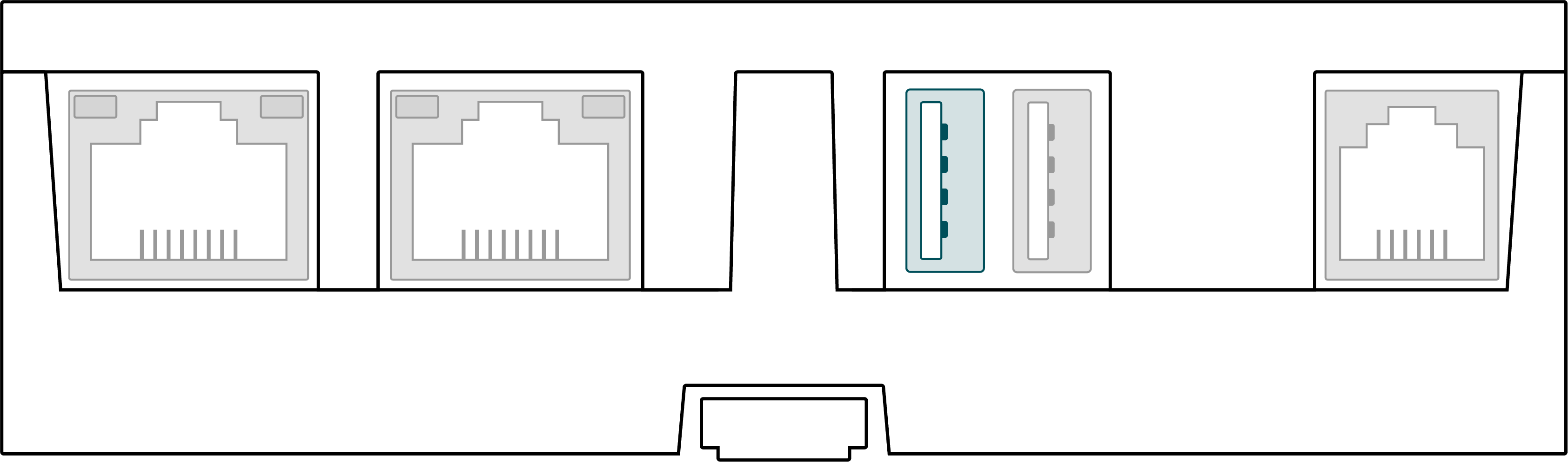
The USB0 port can be used to insert external storage devices into the SolarGatewaySE.
Port specifications
- Up to 500mA current delivery
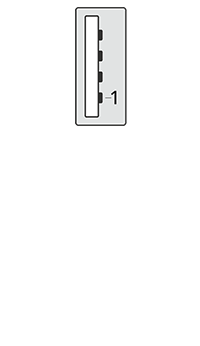
| USB0 Pinning | ||
| Appearance | Pin | Description |
|---|---|---|
| 1 | +5V |
| 2 | D- | |
| 3 | D+ | |
| 4 | GND | |
USB1 Port
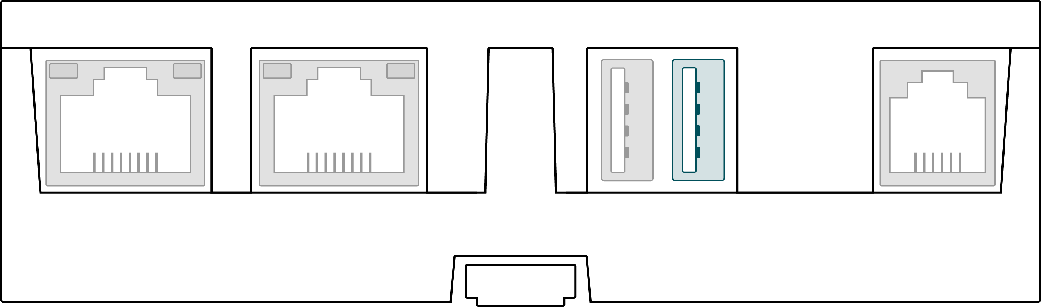
The USB1 port can be used to insert external storage devices into the SolarGatewaySE.
Port specifications
- Up to 500mA current delivery
| USB1 Pinning | ||
| Appearance | Pin | Description |
|---|---|---|
| 1 | +5V |
| 2 | D- | |
| 3 | D+ | |
| 4 | GND | |
P1 Port
The P1 port is used to directly connect to a compatible smart meter.
Port specifications
- Reads meter directly from P1 connection on smart meter
- Support for DSMR 4.0-5.0
- Fixed baudrate of 115200 Baud
- Only usable for unencrypted meter data
Warning
Please make sure the meter connected to P1 is a DSMR 4 or DSMR 5 meter. Older DSMR versions are not supported at the moment.
| P1 Pinning | ||
| Appearance | Pin | Description |
|---|---|---|
| 1 | NC |
| 2 | Data request | |
| 3 | ISOGND | |
| 4 | NC | |
| 5 | Data | |
| 6 | ISOGND | |
Status indicators
Status LED
| Status LED | ||
| LED | LED Status | Description |
|---|---|---|
| Green | Device operational |
| Red | System busy | |
| Blue | Reserved | |

Gateway LED
| Gateway LED | ||
| LED | LED Status | Description |
|---|---|---|
| Green | SolarGatewaySE services are running |
| Yellow | Problem with a service | |
| Red | SolarGatewaySE is not operating | |

External LED
| Extrernal LED | ||
| LED | LED Status | Description |
|---|---|---|
| Green | External devices are ok |
| Yellow | Communication problem | |
| Red | Problem with at least one of the external devices | |

Buttons
UP Button
| Button UP | ||
| Appearance | Press | Action |
|---|---|---|
| Short press | Short press action |
| Long press | Long press action | |

DOWN Button
| Button DOWN | ||
| Appearance | Press | Action |
|---|---|---|
| Short press | Short press action |
| Long press | Long press action | |

BACK Button
| Button BACK | ||
| Appearance | Press | Action |
|---|---|---|
| Short press | Short press action |
| Long press | Long press action | |

OK Button
| Button OK | ||
| Appearance | Press | Action |
|---|---|---|
| Short press | Short press action |
| Long press | Long press action | |

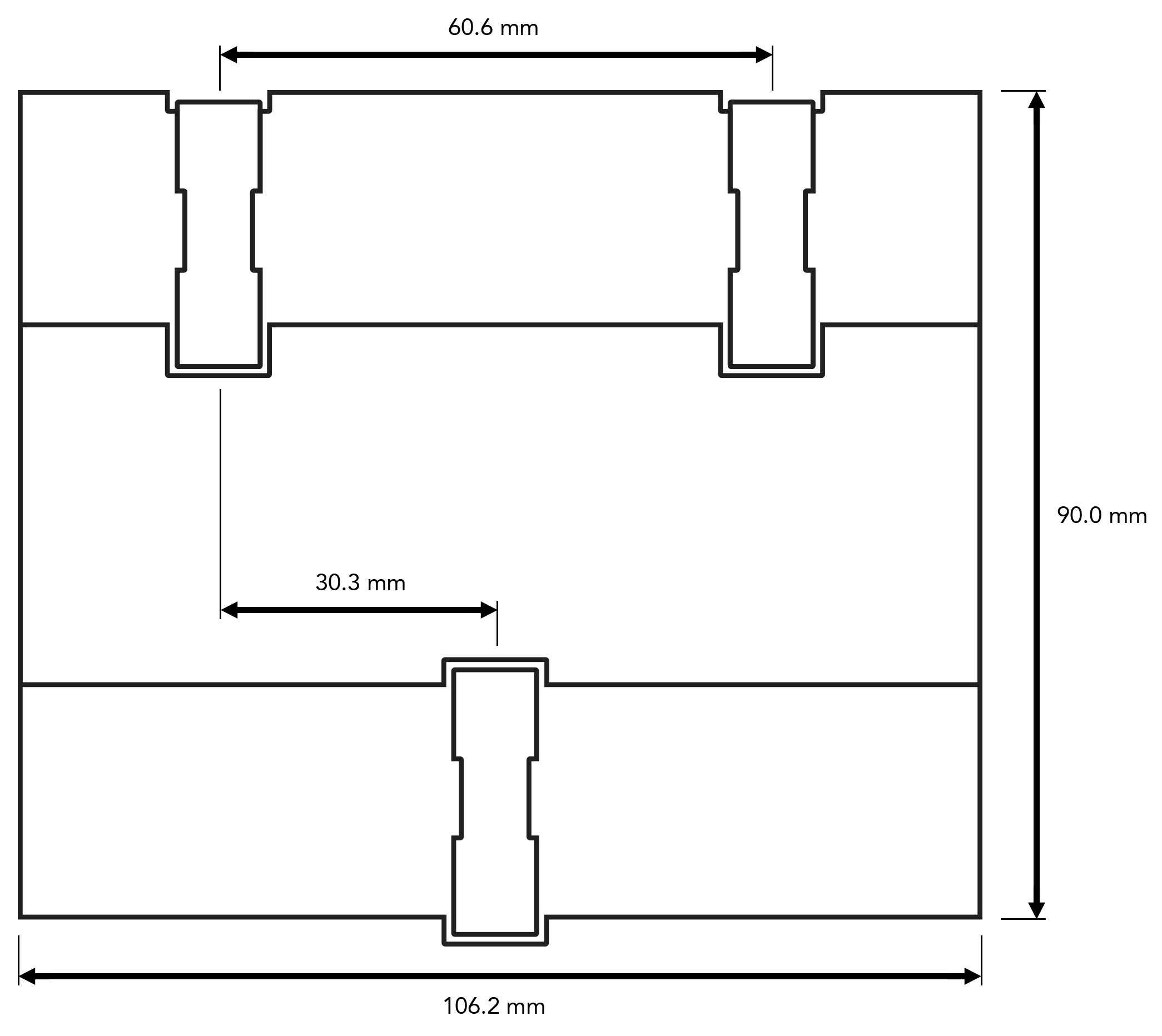
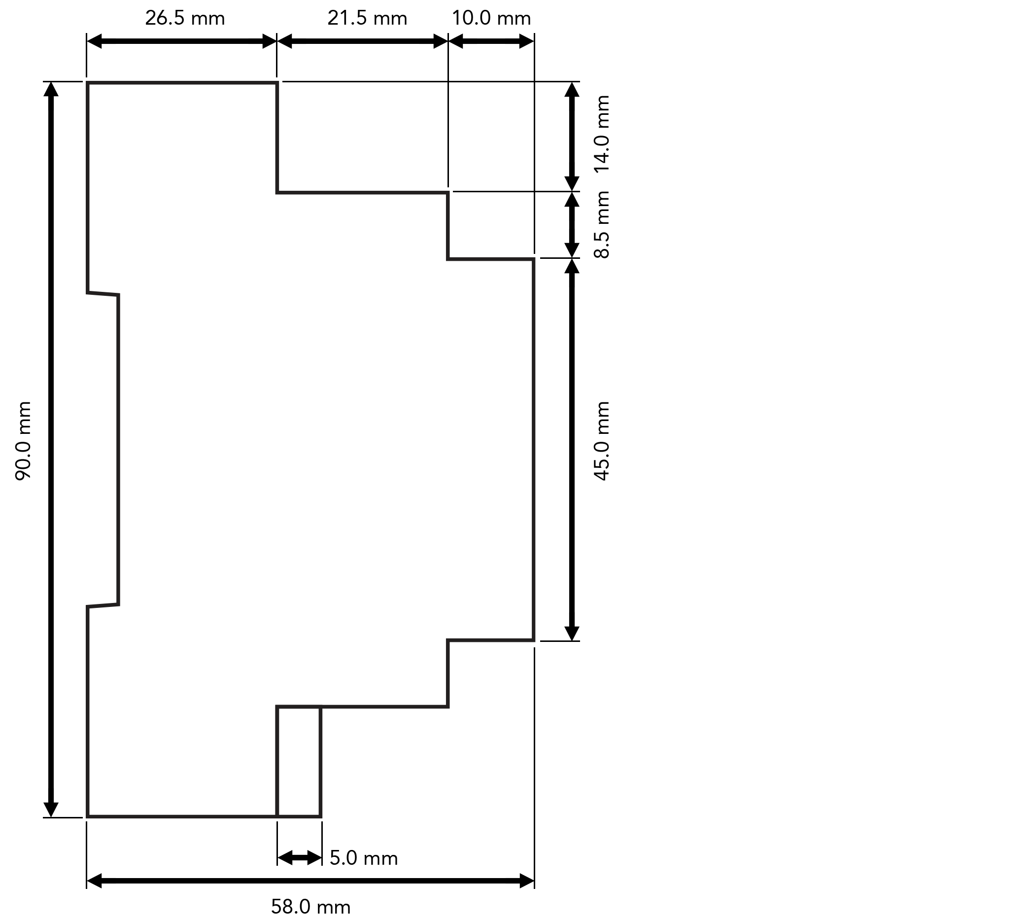
Dimensions
Weight
| PN | Weigth | Unit |
|---|---|---|
| A010 | 335 | gram |
| A010-POE | 355 | gram |
Device installation
Box check
Outer packaging
Check if outer packaging is undamaged before opening it. If there are any signs of damage or abnormality, do not open the package and contact your dealer immediately.
Deliverables
Check if the quantity against packing list is in the packing case. If any component is missing or damaged, contact your dealer.
Note
All provided connectors are already plugged into the device
Required tools


Note
Depending on the specific type of installation and type of environment, extra tools may be required.
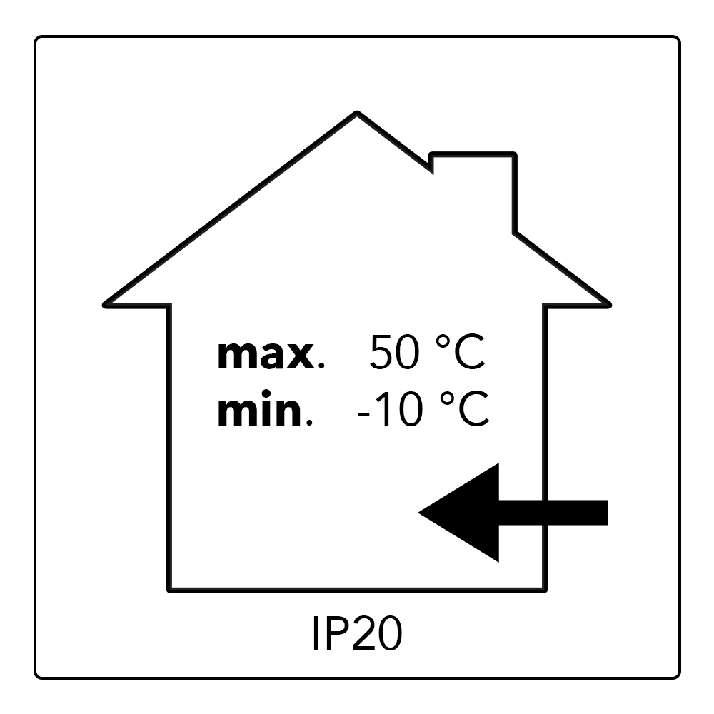
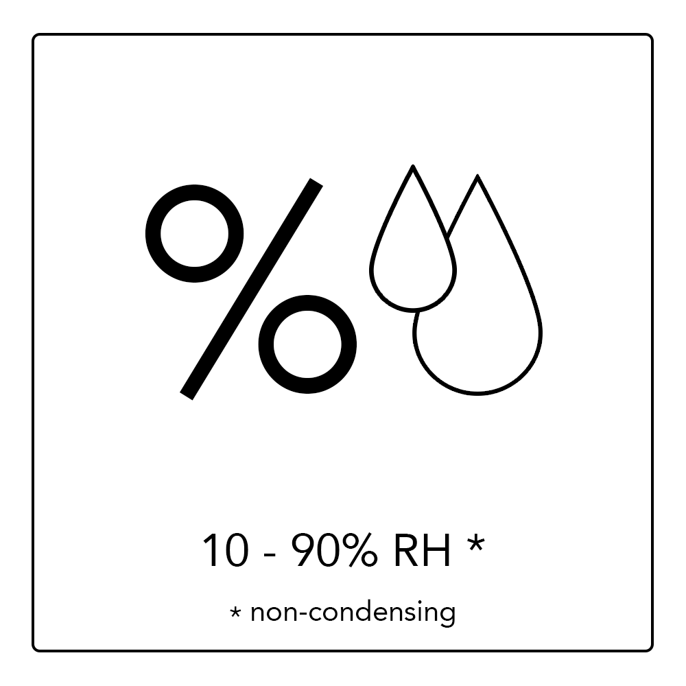
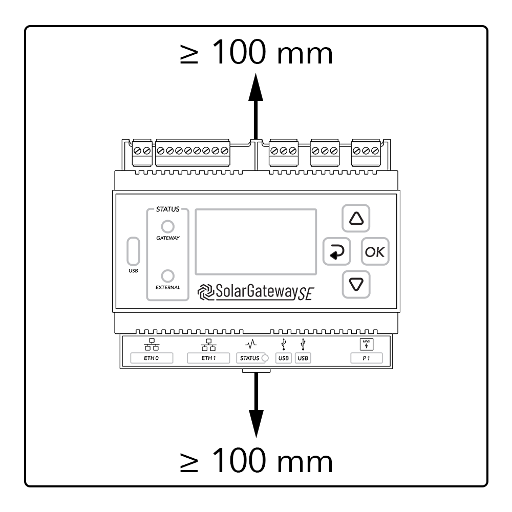
Installation Requirements
Note
Proper installation of the SolarGatewaySE is essential for achieving optimum performance and ensuring easy maintenance. It is crucial to adhere to the recommended height to ensure optimal functionality. Additionally, it is important to meet the minimum object distance, ambient temperature, and humidity requirements to maintain the validity of the warranty. Failure to comply with these guidelines may result in voiding the warranty.
Installing the SolarGatewaySE
The SolarGatewaySE can be wall-mounted or DIN rail-mounted (prefferred).
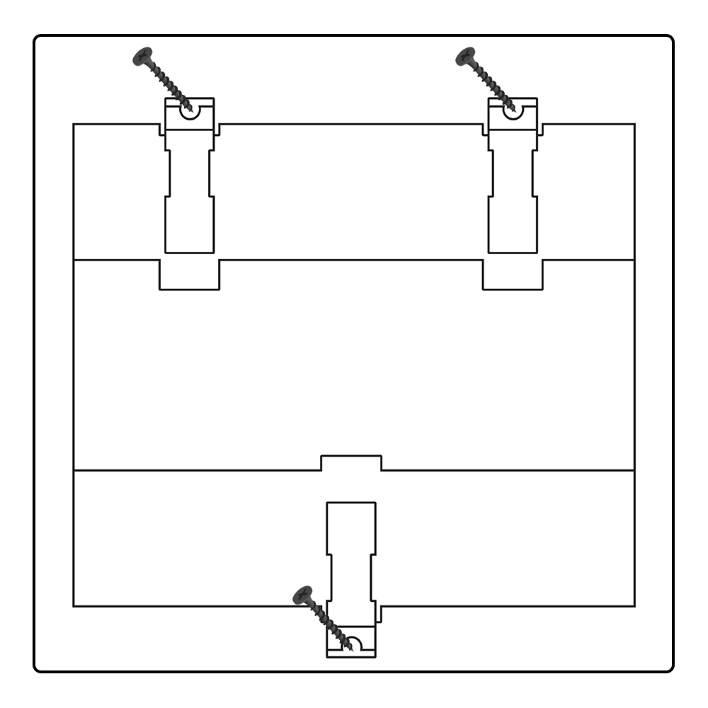
Wall-mounted installation
Warning
The SolarGatewaySE should be installed at a proper height to facilitate operation and maintenance
Install the SolarGatewaySE on a flat and secure wall
DIN rail mounted
Prepare a 35mm standard DIN rail (not included). Ensure that the rail:
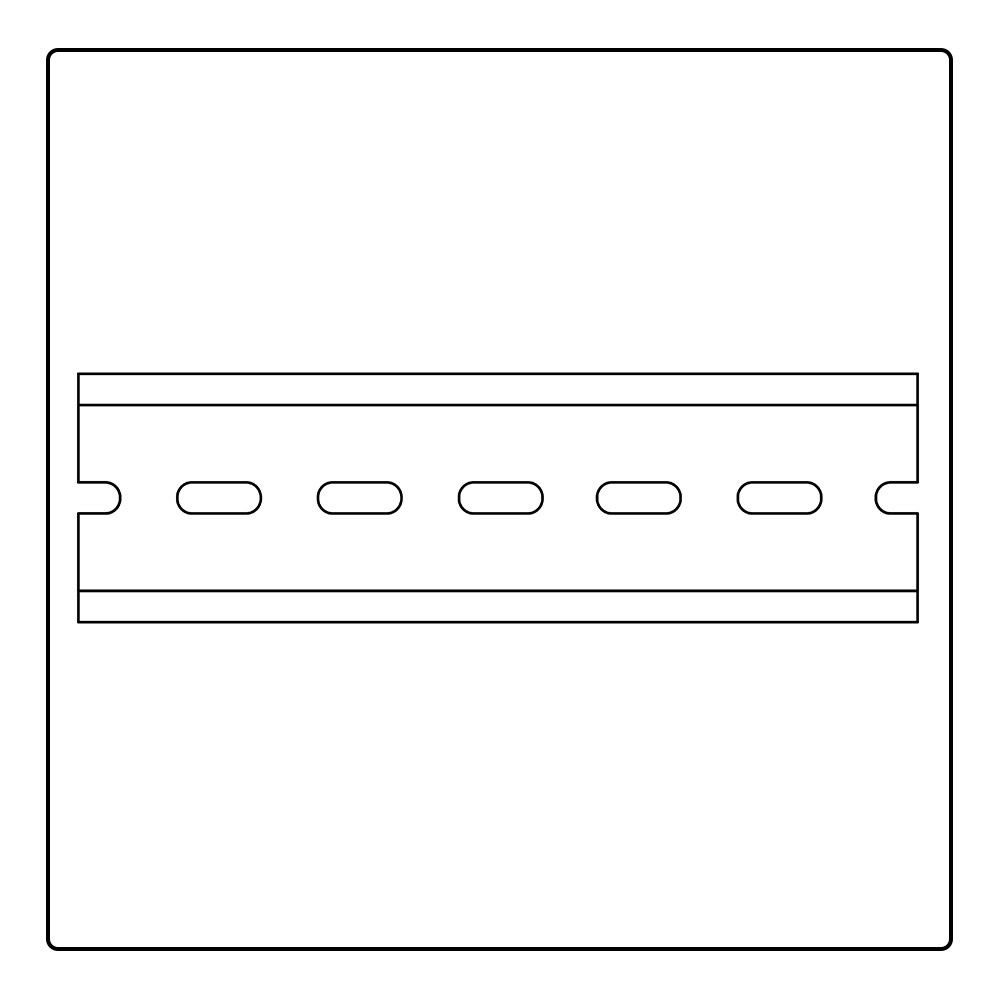
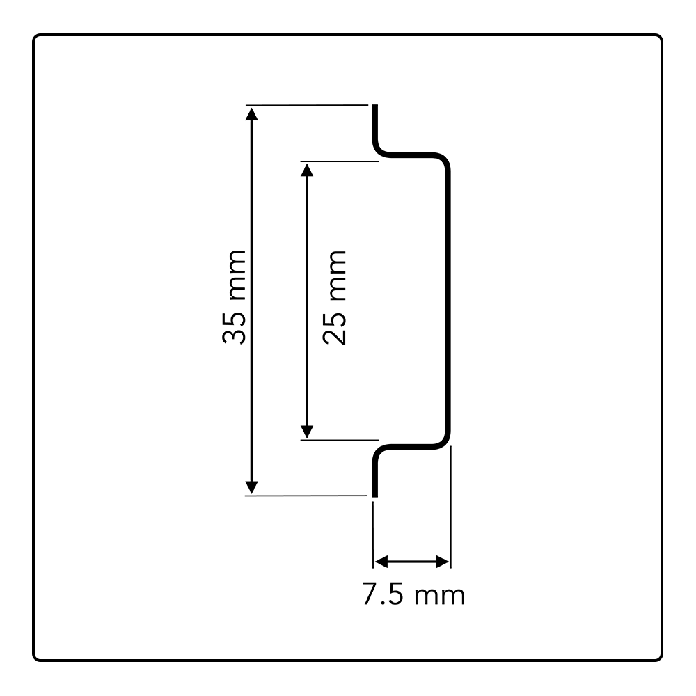
Ensure that the rail:
Has sufficient length for securing the SolarGatewaySE. The recommended effective length is 120 mm or greater.
Has been secured before you install the SolarGatewaySE.
Is correctly terminated, so the SolarGatewaySE can’t slide.
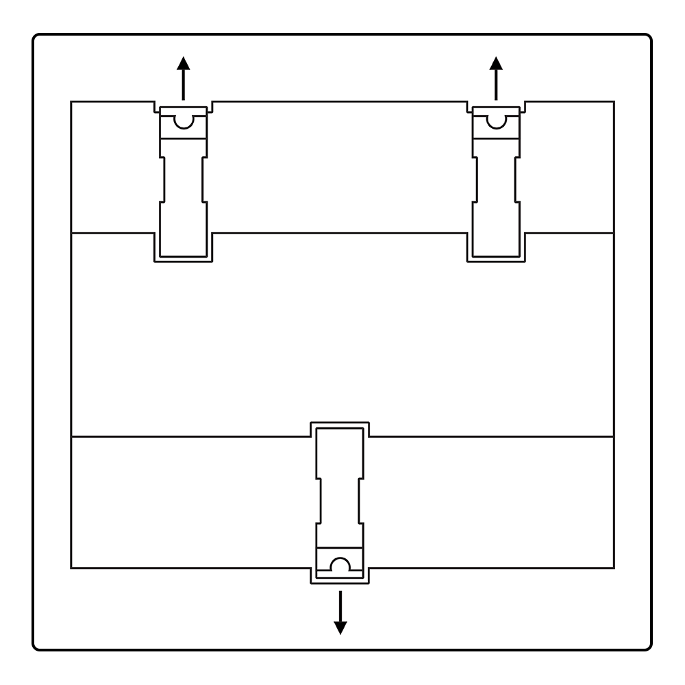
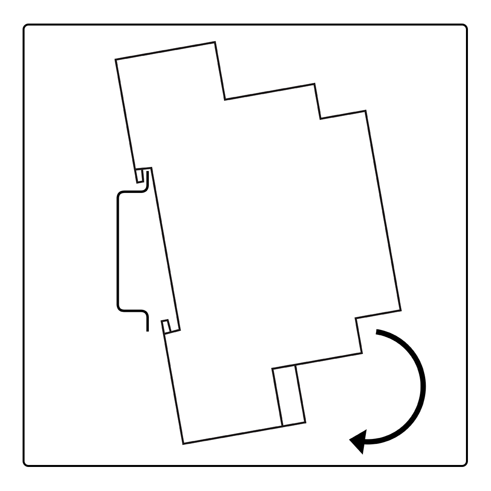
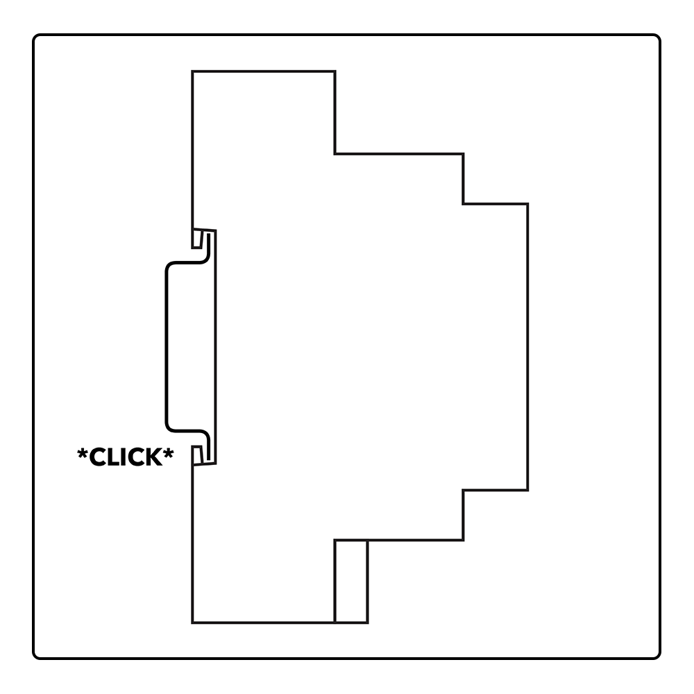
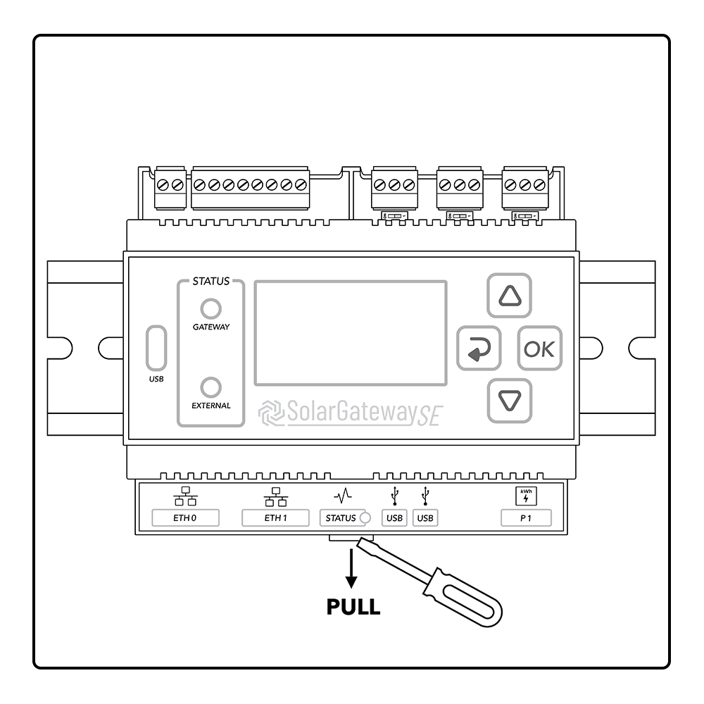
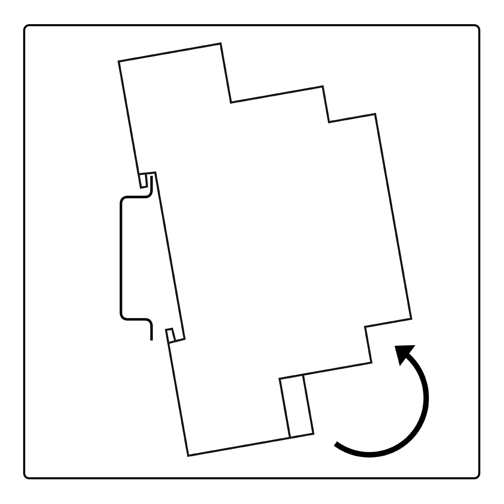
Attach to DIN rail
Remove from DIN rail
Device usage
Menu usage
The SolarGatewaySE device menu is used to configure the device. Multiple inputs are required during these settings. To allow for a standard and generic input option a dedicated input menu is designed. This menu allows for free character input, but it is important to understand the way of working as described in this chapter.
Tip
The SolarGatewaySE also supports remote configuration via the HUB portal when the device is connected to the internet. After adding the device to a namespace, the user is able to setup the device though the HUB web interface.
Menu overview
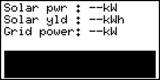
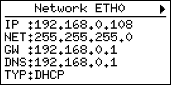
The main page that is shown contains some general information about the installation. This page will automatically be shown when there is no more interaction between user and device. The items shown on this page may vary depending on the configuration. The dark bar shows actual system information.
Menu settings
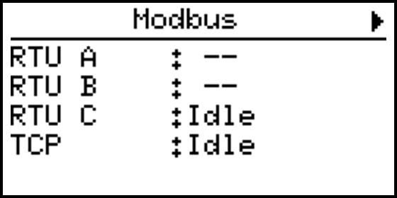
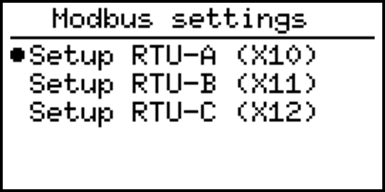
When a menu page contains an arrow in the right corner, it means that there is a settings menu for is. Press the OK butten to open the settings for the selected menu page. The images below show an example of the menu page “Modbus” which contains a settings menu “Modbus settings”.
Device information
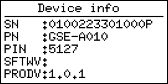
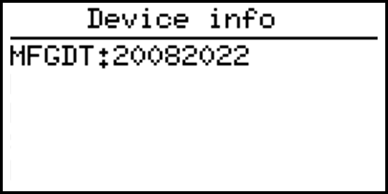
This page shows prododuct information which is identical to the information on the product label. Also current software version is visible in this menu.
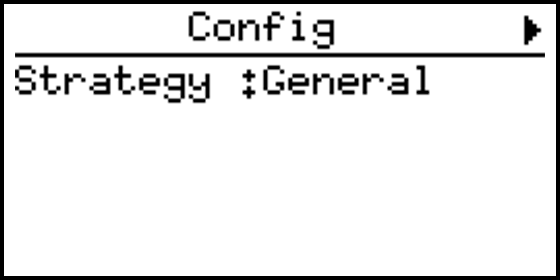
Config
This page will show the active strategy. For example: General. By entering the menu, strategy settings can be changed.
More information about the config settings can be found here: Section 6
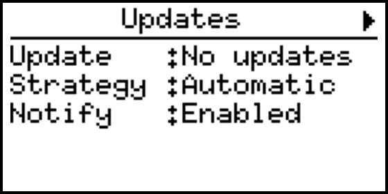
Updates
This menu page shows the current update settings for the device. By entering the menu new device software can directly be installed if available.
More information about the update settings can be found here: Section 7.7
Systeem status
This menu page shows system status information. Internet connection, HUB setup and support information can directly be read from this page.
More information about the system status settings can be found here: Section 7.5
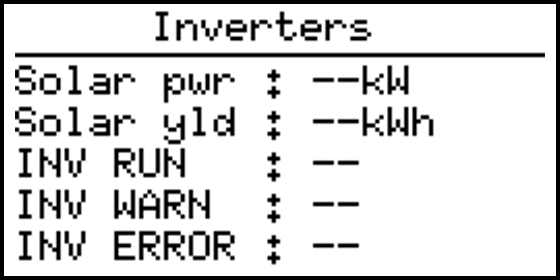
Inverters
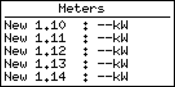
If any inverters are configured, this menu page(s) show the current status for all inverter(s) combined. The AC power per inverter is also listed. Depending on the number of inverters configured, multiple pages are used.
This menu page(s) displays the current status for each inverter. The displayed name of the inverter is the name of the group where it’s in, combined with the inverter address. For example the inverter “New 1.10” is a inverter from the inverter group “New 1” with the inverter address “10”.
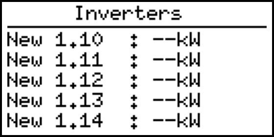
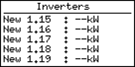
Inverters can be configured in the config settings for inverters explained on page: Section 6.3
Meters
If any meters configured, this menu pages(s) displays the current grid power and current status for each meter. The displayed name of the meter is the name of the group where it’s in, combined with the meter address. For example the meter “New 1.10” is a meter from the meter group “New 1” with the meter address “10”.
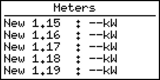
Meters can be configured in the config settings for meters explained on page: Section 6.4
P1 Smart meter
This menu page displays the P1 smart meter status. No meetering values are shown here, only connection related information.
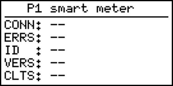
P1 can be configured in the config settings for meters explained on page: Section 6.4.2.1
Modbus
This menu page displays the current modbus status for all the RTU and TCP ports. The individual RTU ports can be configured though this menu.
More information about the Modbus settings can be found here: Section 7.3
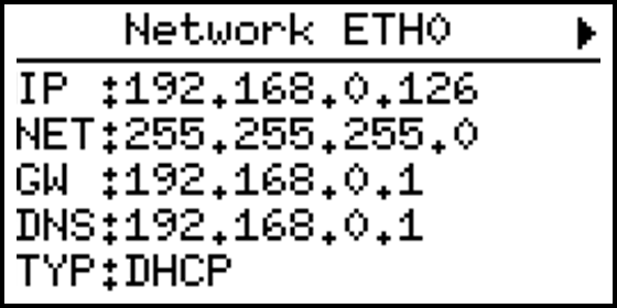
Network ETH0
This menu displays the current ethernet status for the ETH0 connection.
More information about the ETH0 settings can be found on page: Section 7.1
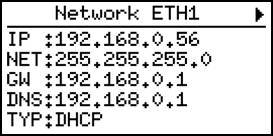
Network ETH1
This menu displays the current ethernet status for the ETH1 connection.
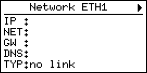
More information about the ETH1 settings can be found on page: Section 7.2
GPIO
This menu page displays the GPIO status.
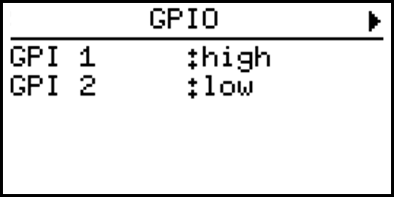
More information about the GPIO settings can be found on page: Section 7.4
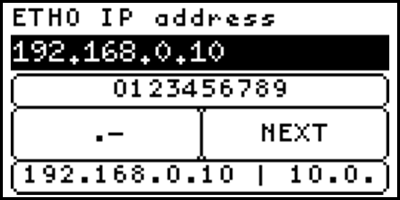
Input description
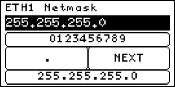
On the SolarGatewaySE there are multiple inputs required like IP addresses, IP address ranges and names. The steps below will explain how to use the buttons to insert characters.
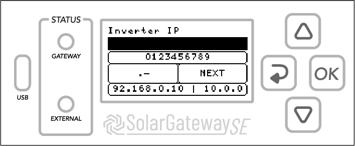
Input options
Use the buttons on the SolarGatewaySE to select one of the four input options related to the position of the pressed button.
For example: the UP button selects and highlight the numeric input.
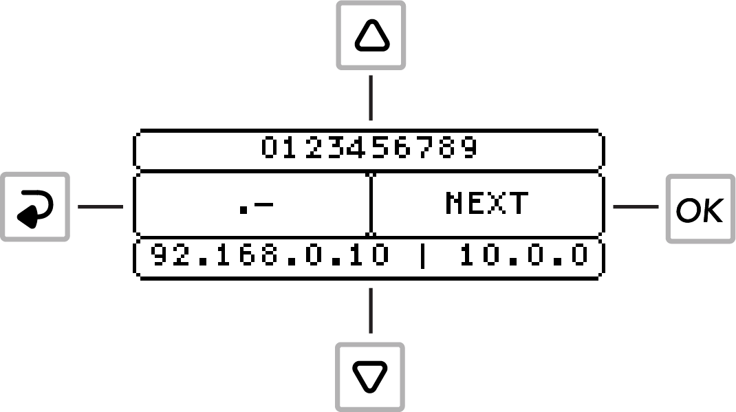
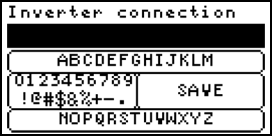
Select characters
When an input option is selected, use the UP and DOWN buttons to navigate and select a character or pre-defined value like and IP-address. Press the OK button or wait 3 seconds to confirm the selected character or value. Characters now appear in the input field as shown below.
Remove characters
While one of the input option is selected, press the BACK button to remove the last character or hold the OK button to clear all input.
Uppercase
It is possible to use uppercase characters. Hold the UP button to activate uppercase characters, and hold it again to switch back.
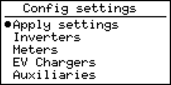
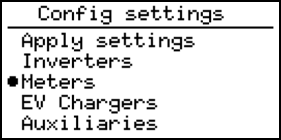
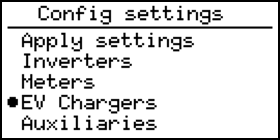
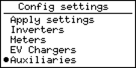
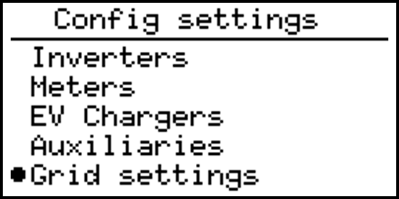
Configuration settings
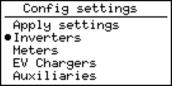
On the “Config settings” page the basic system settings are done. The following configuration item are found:
- Apply settings
- Inverters
- Meters
- EV Chargers
- Auxiliaries
- Grid settings
- Grid voltage control
- Active power control
- Arc detection
- GPIO control
- Help

Apply settings
All settings in the config menu can be changed without directly effecting the current function of the SolarGatewaySE. When settings are changed, the changes must by applied using this menu. Applying the settings can be done selecting one of multiple strategies. Each strategy has predefined controllers and certain required settings to be set. After applying a new strategy the system will check all requirements and only if all requirements for the strategy are met, the new strategy is applied.
Activate config
This configuration will activate all settings, a strategy must be selected. Changed settings are stored, but not applied until the wanted strategy is selected and correctly applied. If a faulty configuration is found, the selected strategy returns an error, and the system function is not changed. Only if the selected strategy is correctly configured, the new configuration is applied and the old configured strategy is replaced by the new one.
Select strategy
To activate all settings, a strategy needs to be selected. The current implemented strategies are:
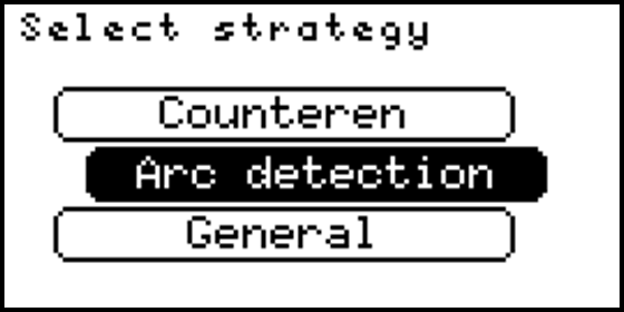
Counteren
Counteren will provide the stand-alone counter controller using a grid meter, inverters and a pyrano sensor. The maximum configured grid return power is used as maximum power. Until a measured radiation of 500 \(\frac{W}{m^2}\) the export limit is the configured grid return power. Between a measured radiation of 500 \(\frac{W}{m^2}\) and 750 \(\frac{W}{m^2}\) the export limit is linearly reduced from the configured grid return power to 0 kW. Therefore, at a measured radiation of >=750 \(\frac{W}{m^2}\) the export limit is 0 kW.
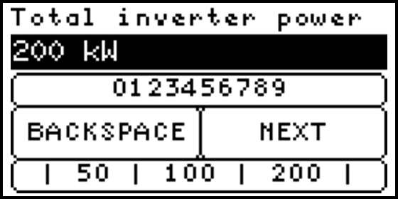
During the activation of the Counteren strategy, the total installed inverter power is requested. This is the sum of the AC output power of all connected inverters. This value is used for correct control of the power. For correct functioning of the Counteren strategy, please make sure the inverter power is correctly entered.
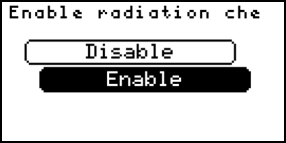
The SolarGatewaySE is able to check the validity of the measured solar radiation, using the actual measured solar radiation and the actual solar power, combing both values using the total PV power configured in the inverter groups. When the generated solar power becomes larger than could be possible with the actual radiation and configured PV power, an error is triggered and the export limit is fixed to 0kW. The error can be recovered in the Counteren menu.
When the error is triggered it could indicate a dirty or not correctly functional radiation sensor and therefore wrong counter limits. If needed the check can be disabled while the Counteren strategy is applied.
Arc detection
Arc detection will only provide the arc detection functionality using an external arc detection. This strategy will not implement any export or import limiter. This allows for easy and fast arc detection integration in existing systems.
General
General will provide all required controllers, except for the countering controller. This strategy uses the entered solar power per group and grid export limits to create (if required) an export controller. At least one grid meter is required to do so.
Inverter configuration
This configuration allows the user to configure the connected inverters (if any). multiple groups can be made, where each group connects to the same type of meters, through the same physical interface.
Inverter groups
The “Inverter groups” page will show all existing inverter groups. There is one pre-set group called “New 1” that isn’t configured yet, this group is automatically added by removing your last existing group.
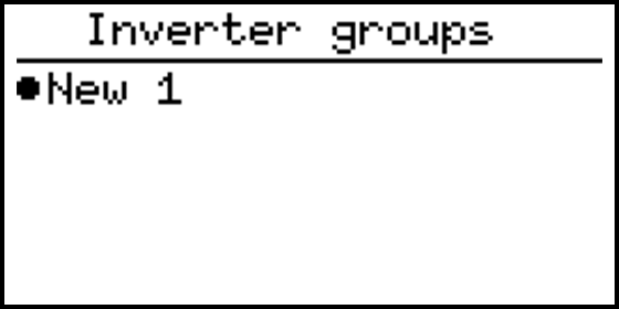
It is possible to add more groups, rename the existing groups, duplicate a specific group or delete one group. Select a group and hold the OK button to trigger this options.
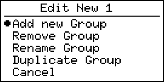
Note
To add more than 15 inverters, a licence is needed, inverter ranges in different groups will be counted together as single inverters.
Configure inverter group
The following inputs are required to configure a group of inverter(s).
- Inverter connection
- Address range
- Inverter type
- Inverter IP address
- Inverter TCP port
- Strings per inverter
- Total number of solar panels
- Peak power per panel
Note
Inverter IP and TCP port will only be asked when the selected connection type of the inverter is TCP/IP.
Inverter connection
Select the connection type of the to be configured inverter(s)
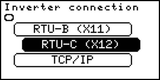
The following connection types can be selected:
- RTU-A (X10)
- RTU-B (X11)
- RTU-C (X12)
- TCP/IP
Inverter slave addresses
Insert the address range of the to be configured inverter(s). It is possible to seperate addresses with the use of “,” or to define a range with the use of “-”. For example: The input “1,2,4-10” will set a address range from 1 to 10 except 3.
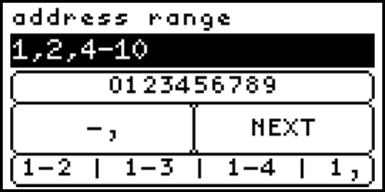
Note
An address may only occure once per RTU port. Meters and inverters could be connected to the same RTU port, as long as baudrate settings are identical and each connected slave has a unique address.
Inverter type
Select here the type or brand of the to be configured inverter.
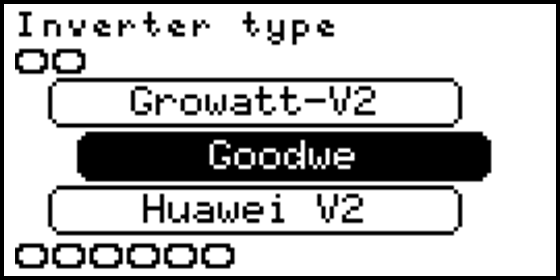
The following types can be selected:
- INVT
- Growatt-V1
- Growatt-V2
- Huawei V2
- Huawei V3
- SMA tripower
- SMA Sunspec
- SolarEdge
- Solax 3phase
- Sofar G1
- Sofar G2
- Sofar G3
- Sofar G3 Hyb
- Delta Sunspec
- ABB Trio
- SAJ Plus series
- SMA datalogger (only combined PAC, Yield and power control)
- ABB PVS
- Altilia
- Eaton Xstorage (no control function at the moment)
- Deye
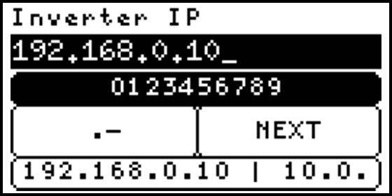
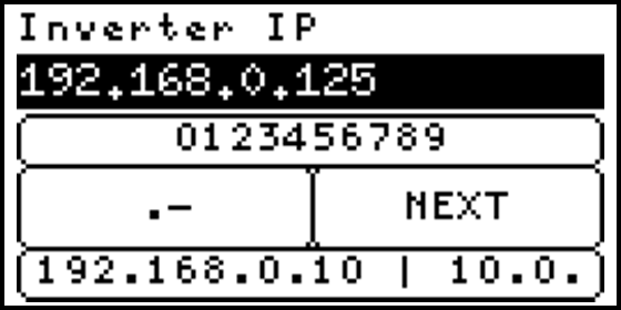
Inverter IP
Insert the IP address of the to be configured inverter(s). For example: “192.168.0.125”.
It is possible to define multiple addresses in the address range and only one IP address if all addresses can be reached through the same TCP/IP slave.
If each address has its own TCP/IP slave and a dedicated IP address, an IP range can be entered. To enter a range, the first IP address is entered followed by a ‘,’ or a ‘-’ and the last octet of the last IP address.
For example, if the address range is set to 1-4 (or 1, 2, 3, 4) and each address has a dedicated IP address, the IP input could be 192.168.0.10-13 (or 192.168.0.10, 11, 12, 13). The SolarGatewaySE will then translate this into the following IP addresses: 192.168.0.10, 192.168.0.11, 192.168.0.12, and 192.168.0.13.
Note
It should be noted that when multiple IP addresses are defined, the number of defined addresses must be equal to the number of defined IP addresses. Failure to meet this criteria will result in an error when the settings are applied.
Note
Inverter IP will only be asked when the inverter connection type is TCP/IP.
Inverter TCP port
Insert the TCP port of the to be configured inverter(s). For example: “502”
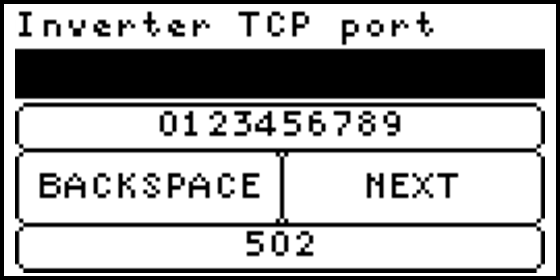
Note
Inverter port will only be asked when the inverter connection type is TCP/IP.
Strings/MPPT per inverter
Insert the number of individual string or MPPT data which should be read for every inverter connected to the group. Basically the number of individually monitored strings or MPPTs per inverter is entered here.

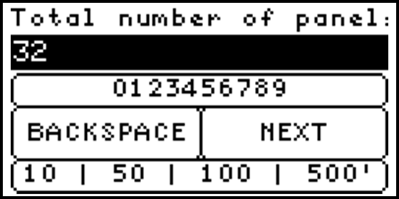
Installed solar panels
Enter the total number of solar panels installed for this group of inverter(s).
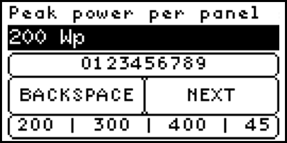
Peak power per panel
Enter the peak power per panel for the installed solar panels. The total solar power (Installed solar panels * Peak power per panel) is used to calculate the required export limit controllers. If different panels are used, make sure the total entered power (Installed solar panels * Peak power per panel) is correct.
Meter configuration
This configuration allows the user to configure the connected meters (if any). multiple groups can be made, where each group connects to the same type of meters, through the same physical interface.
Note
Make sure the meter active power orientation is in the right convention used within the SolarGatewaySE.
A positive active power is always interpreted as a consumed power, while a negative active power is interpreted as a returned power.
Warning
When peakshaving for PV generation is active, the active power orientation for the grid meter should be correct. The SolarGatewaySE is only limiting (on grid power or grid current) the connected inverters when the measured grid power is negative (returning power to the grid).
Meter groups
The “Meter groups” page will show all existing meter groups. There is one pre-set group called “New 1” that isn’t configured yet, this group is automatically added by removing your last existing group.
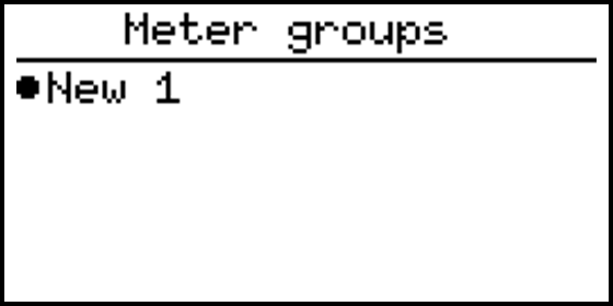
It is possible to add more groups, rename the existing groups, duplicate a specific group or delete one group. Select a group and hold the OK button to trigger this options.
Note
To add more than 15 meters, a licence is needed, meter ranges in different groups will be counted together as single meters.
Configure meter group
The following inputs are required to configure a group of meter(s).
- Meter connection
- Address range
- Meter type
- Meter location
- Meter IP address
- Meter TCP port
Note
Address range will only be asked when the selected connection type of the meter(s) is RTU or TCP/IP.
Note
Meter IP address and TCP port will only be asked when the selected connection type of the meter(s) is TCP/IP.
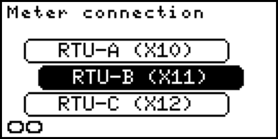
Meter connection
Select the connection type of the to be configured meter(s) the options are:
- RTU-A (X10)
- RTU-B (X11)
- RTU-C (X12)
- P1
- TCP/IP
Note
When meter(s) connection is P1, the only extra setting needed to complete are extra connected P1 meters and meter location.
Meter slave addresses
Insert the address range of the to be configured meter(s). It is possible to seperate addresses with the use of “,” or to define a range with the use of “-”. For example: The input “1,2,4-10” will set a address range from 1 to 10 except 3.
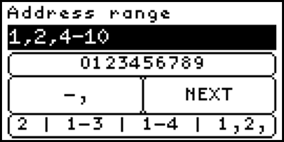
Note
An address may only occure once per RTU port. Meters and inverters could be connected to the same RTU port, as long as baudrate settings are identical and each connected slave has a unique address.
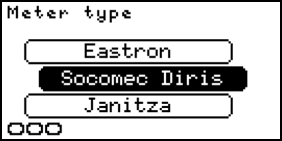
Meter type
Select here the type or brand of the to be configured meter. The following type or brands are available to select:
- Eastron
- Socomec Diris
- Socomec Countis (No THD measurement)
- Janitza
- Hager EC
- Weidemuller EM610
- ABB B23/B24 (No THD measurement)
- Sneider NSX
- Sneider PM series
- Chint DTSU666
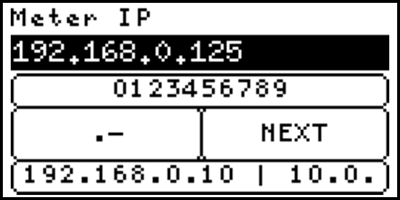
Meter IP
Insert the IP address of the to be configured meter(s). For example: “192.168.0.125”.
It is possible to define multiple addresses in the address range and only one IP address if all addresses can be reached through the same TCP/IP slave.
If each address has its own TCP/IP slave and a dedicated IP address, an IP range can be entered. To enter a range, the first IP address is entered followed by a ‘,’ or a ‘-’ and the last octet of the last IP address.
For example, if the address range is set to 1-4 (or 1, 2, 3, 4) and each address has a dedicated IP address, the IP input could be 192.168.0.10-13 (or 192.168.0.10, 11, 12, 13). The SolarGatewaySE will then translate this into the following IP addresses: 192.168.0.10, 192.168.0.11, 192.168.0.12, and 192.168.0.13.
Note
It should be noted that when multiple IP addresses are defined, the number of defined addresses must be equal to the number of defined IP addresses. Failure to meet this criteria will result in an error when the settings are applied.
Note
Meter(s) IP will only be asked when the meter(s) connection type is TCP/IP.
Meter TCP port
Insert the port of the to be configured meter(s). For example: “502”
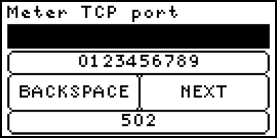
Note
Meter(s) port will only be asked when the meter(s) connection type is TCP/IP.
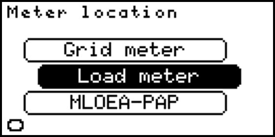
Meter location
Select here the meter(s) location of the to be configures meter(s), options are:
- Grid meter
- Load meter
- MLOEA-PAP
- MLOEA-SAP
Note
All meters configured as Grid meter should measure the same power. Multiple meters configured as Grid meter can be used as redundant measurement. If the measurement in one of the Grid meters is not corresponding with the measurements of the other, an error is raised and inverters are safely reduced to there safe power. This to prevent the export limit to exceed the configured limit.
Note
For a MLOAE grid connection, both meters (MLOEA-PAP and MLOEA-SAP) need to be configured. The SolarGatewaySE will calculate the actual grid power and currents by combining both meters. Setting up only one of the two MLOEA meters result in a incorrect configuration.
Split solar/grid
Availble when load meter is selected. Enabling this function will create two new meter registers, one for the energy directly consumed out of Solar energy and one register for the energy directly consumed out of grid energy. Two possible system configurations are possible.
System with at least one grid meter and 1 or more load meters. The system will count all energy sourced by the grid meter as grid energy, all energy consumed but not sourced by the grid meter is counted as solar energy.
System without a grid meter, in this case the power delivered by the connected solar inverters is used to calculate the solar energy. All other energy is counted as grid energy.
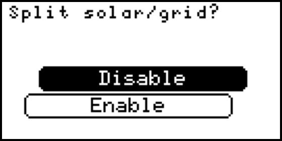
Note
To activate the split solar/grid energy meters at least one grid meter or one solar inverter should be connected. An error is raised during setting activation when both (grid meter and solar inverter) are not configured.
EV Chargers
This configuration will define all EV Charger(s) settings. (INTRO ABOUT EV CHARGERS)
EV Charger groups
The ‘EV Charger groups’ page will show all existing EV Charger groups. There is one pre-set group called ‘New group’ that isn’t configured yet, this group is automatically added by removing your last existing group.

It is possible to add more groups, rename the existing groups, duplicate a specific group or delete one group. Select a group and hold the OK button to trigger this options.
Note
To add more than 5 EV Chargers, a licence is needed. EV Charger ranges in different groups will be counted together as single EV Chargers.
configure EV Charger group
The following inputs are required to configure a group of EV Chager(s).
- EV Charger connection
- EV Charger slaves
- EV Charger type
- Min. charge current
- Max. charge current
- Set prio
- EV Charger IP
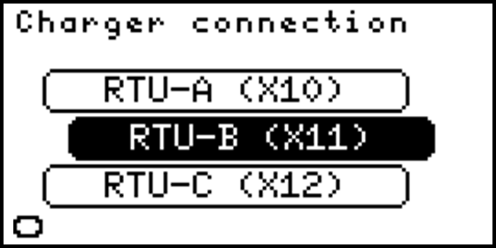
EV Charger connection
Select the connection type of the to be configured EV Charger(s) the options are:
- RTU-A (X10)
- RTU-B (X11)
- RTU-C (X12)
- TCP/IP
EV Charger slave addresses
Enter the slaves for the EV Charger(s). It is possible to seperate slaves with the use of “,” or to define a range with the use of “-”. For example: The input “1,2,4-10” will set a the slaves 1 to 10 except 3.

EV Charger type
Select here the type or brand of the to be configured EV Charger(s). The following type or brands are available to select:
- Orbis
- ABB Terra
- Etrel INCH

Min. charge current
Select the minimum charge current which is send to the device during import limitation. If the current is more than 0, the charger will not stop charging, even if the configured import limit is exceeded. The configured minimum charge current should be equal to or less than Max. charge current.

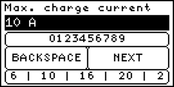
Max. charge current
Select the maximum charge current which is send to the device when there is no import limit. The configured minimum charge current should be equal to or less than Max. charge current.
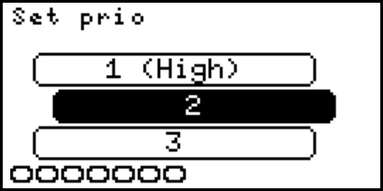
Set prio
The priority for the EV charger current can be set. When power for consumption is available, the SolarGatewaySE will increase loads depenend on their priority. A high priority (low number) is released first and reduced last. Therefore, an EV charger with priority 1 always has the “Min. charge current” available, when the system limits allow it, the current is released to “Max. charge current”. Any other EV charger with priority 2 or higher has the “Min. charge current” available, and will only increase the current if system limits allow it, and all chargers with a lower priority number are fully released.
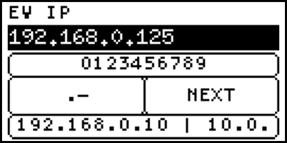
EV Charger IP
Insert the IP address of the to be configured EV Charger(s). For example: “192.168.0.125”.
It is possible to define multiple addresses in the address range and only one IP address if all addresses can be reached through the same TCP/IP slave.
If each address has its own TCP/IP slave and a dedicated IP address, an IP range can be entered. To enter a range, the first IP address is entered followed by a ‘,’ or a ‘-’ and the last octet of the last IP address.
For example, if the address range is set to 1-4 (or 1, 2, 3, 4) and each address has a dedicated IP address, the IP input could be 192.168.0.10-13 (or 192.168.0.10, 11, 12, 13). The SolarGatewaySE will then translate this into the following IP addresses: 192.168.0.10, 192.168.0.11, 192.168.0.12, and 192.168.0.13.
Note
It should be noted that when multiple IP addresses are defined, the number of defined addresses must be equal to the number of defined IP addresses. Failure to meet this criteria will result in an error when the settings are applied.
Note
EV Charger(s) IP will only be asked when the EV Charger(s) connection type is TCP/IP.
EV Charger port
Insert the port of the to be configured EV Charger(s). For example: “502”

Note
EV Charger(s) port will only be asked when the EV Charger(s) connection type is TCP/IP.
Auxiliaries
This configuration will define all Auxiliaries settings. (INTRO)
Auxiliaries groups
The ‘Auxiliaries groups’ page will show all existing Auxiliaries groups. There is one pre-set group called ‘New group’ that isn’t configured yet, this group is automatically added by removing your last existing group.
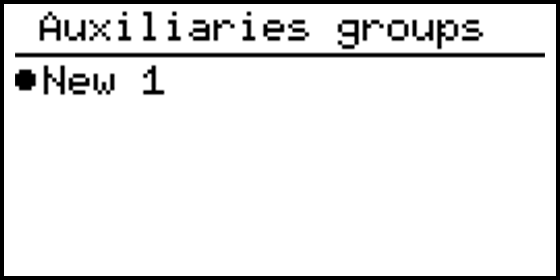
It is possible to add more groups, rename the existing groups, duplicate a specific group or delete one group. Select a group and hold the OK button to trigger this options.
Note
To add more than 15 Auxiliaries, a licence is needed. Auxiliaries ranges in different groups will be counted together as single Auxiliaries.
configure Auxiliaries group
The following inputs are required to configure a group of Auxiliaries:
- Auxiliaries connection
- Auxiliaries slaves
- Auxiliaries type
- Auxiliaries IP
Auxiliaries connection
Select the connection type of the to be configured Auxiliaries the options are:
- RTU-A (X10)
- RTU-B (X11)
- RTU-C (X12)
- TCP/IP

Auxiliaries slave addresses
Enter the slaves for the Auxiliaries. It is possible to seperate slaves with the use of “,” or to define a range with the use of “-”. For example: The input “1,2,4-10” will set a the slaves 1 to 10 except 3.
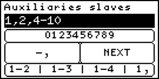
Note
An address may only occure once per RTU port. Slaves of diffrent types could be connected to the same RTU port, as long as baudrate settings are identical and each connected slave has a unique address.
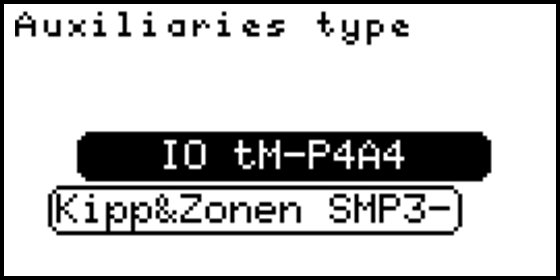
Auxiliaries type
Select the connection type of the to be configured Auxiliaries the options are:
- IO TM-P4A4 (Modbus GPIO module)
- Kipp&Zonen SMP3-A (Pyrano sensor)
- Huawei SL pyrano (Pyrano sensor connected to the Huawei smartlogger)
Note
If a pyrano sensor connected to the Huawei smartlogger is configured, use the configured pyrano sensor address configured in the smartlogger.
Auxiliaries IP
Insert the IP address of the to be configured Auxiliaries. For example: “192.168.0.125”.
It is possible to define multiple addresses in the address range and only one IP address if all addresses can be reached through the same TCP/IP slave.
If each address has its own TCP/IP slave and a dedicated IP address, an IP range can be entered. To enter a range, the first IP address is entered followed by a ‘,’ or a ‘-’ and the last octet of the last IP address.
For example, if the address range is set to 1-4 (or 1, 2, 3, 4) and each address has a dedicated IP address, the IP input could be 192.168.0.10-13 (or 192.168.0.10, 11, 12, 13). The SolarGatewaySE will then translate this into the following IP addresses: 192.168.0.10, 192.168.0.11, 192.168.0.12, and 192.168.0.13.
Note
It should be noted that when multiple IP addresses are defined, the number of defined addresses must be equal to the number of defined IP addresses. Failure to meet this criteria will result in an error when the settings are applied.
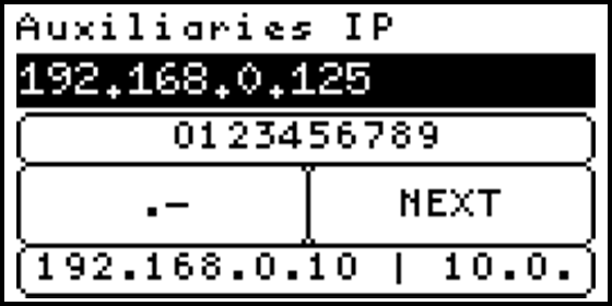
Note
Auxiliaries IP will only be asked when the Auxiliaries connection type is TCP/IP.
Auxiliaries port
Insert the port of the to be configured Auxiliaries. For example: “502”
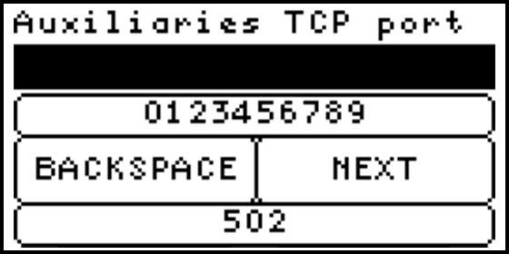
Note
Auxiliaries port will only be asked when the Auxiliaries connection type is TCP/IP.
Grid settings
In this configuration power and current limits for the plant can be defined.
Grid settings configuration
The following inputs are required to configure the grid settings:
- Grid current max
- Grid + power max
- Grid - power max
Grid current max
Enter the maximum allowed grid current for this plant. For example, the mains connection is 3x250 A, fill-in 250.
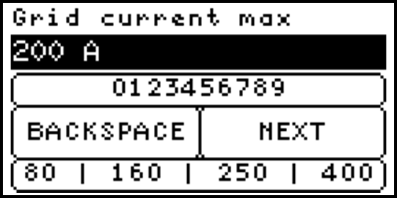
Tip
This is typically the value of the main fuse.
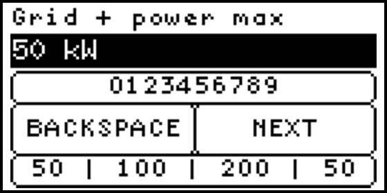
Grid + power max
Enter the maximum active power which might be consumed from the grid. For example: 50 kW.
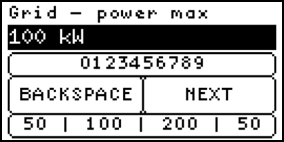
Grid - power max
Enter the maximum active power which might be exported to the grid. For example: 100 kW. The SolarGatewaySE will implement export limitation controllers for configured solar inverters if the configured solar power exceeds the configured limit.
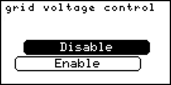
Grid voltage control
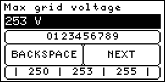
The grid voltage control can be enabled to apply an active power controller in the SolarGatewaySE, regulating the measured grid voltage. The maximum line-neutral grid phase voltage is determined, if this voltage is larger than the configured maximum grid voltage, the inverter active power setpoint is reduced (Using a fixed PI controller). This will limit the active power and therefore lower the grid voltage.
Tip
The grid voltage measured by the inverter is likely to be higher than the voltage at the grid entrance or grid meter location. Hence, it is important to ensure that the maximum allowable grid voltage set in the inverter is higher than the configured maximum grid voltage in the SolarGatewaySE.
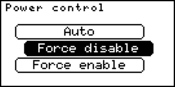
Active power control
By default, the configured number and power of the solar panels, together with the configured maximum grid return power and maximum grid current let the SolarGatewaySE decide if an active power or current controller is required for the configuration. By default an plant control active power controller is also implemented. As user this default configuration can be altered, by changing the Active power control setting.
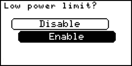
The “low power limit” is disabled by default. This function can be enabled if the maximum generated solar power should be continiously controlled (even when the grid power or current is not close to the limit). This function prevents large peaks when solar power suddenly increases but also increases the inverter ramp-up time. Enabeling this option results in significantly lower peak powers. The total configured inverter power is required to correctly use this function. The function can’t correctly operate when not all inverters are active, if one of the inverters is not active, the function will temporary be disabled.
- Auto: (Default) depending on the configured limits an active power and/or current controller is implemented
- Force disable: all power controllers are disabled! Plant control, export limit control and grid voltage control is not possible. Be carefull using this configuration!
- Force enable: enables the plant control, active power and grid current controller independent of the amount of solar power configured. Using this setting the maximum reduction value can be limited by the user.
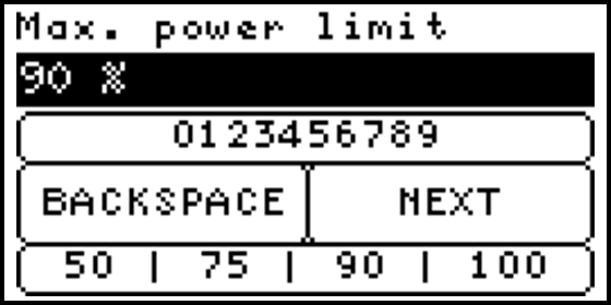
Setting the maximum power limit to less than 100% will consistently restrict the inverters maximum output power to the configured percentage. Consequently, the maximum output power of the inverters will never be attained, even if the grid current and grid negative power have not yet reached their limits yet.
For Auto and Force enable the following options are available to configure low power limit:
Tip
For systems with peak-shaving for a limited main connection, it is adviced to enable the low power limit option. This prevents high peak currents which may trip the mains fuse.
Warning
Setting the “Force disable” option will disable all active power controllers. There will be no grid current, power or voltage control done by the SolarGatewaySE. Also power control via plant control is disabled! Therefore inverters will not be limited when EPEX price control is active.
Arc detection
This configuration will define the external arc detection settings. By default external arc detection is disabled. Keep in mind, any GPIO used to connect to the external arc detection should by true when no arc is detected!
Arc detection configuration
The following inputs are required to complete Arc detection configuration:
- Input type
- Minimum PAC
- Inverter address
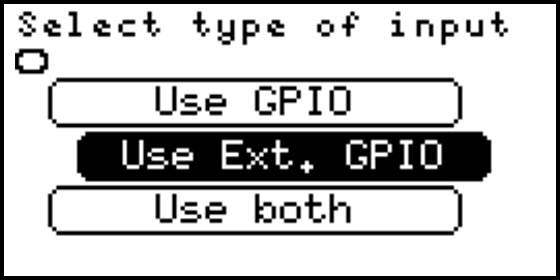
Input type
Select the input type for Arc detection, options are:
- Deactivate
- GPIO (use onboard GPIO for max 2 inverters)
- Ext. GPIO (use modbus GPIO modules for multiple external arc detections)
- Both (Use as well the internal GPIO as external GPIO modules)
Tip
The deactive option will deactivate arc detection, even if the Arc detection strategy is selected. Arc detection is deactivated by default.
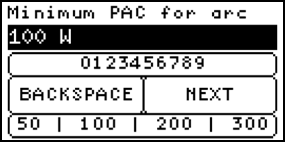
Minimum PAC
Enter the minimum PAC (Inverter AC power) required per inverter for an arc detection. If the AC power of the inverter is not at least as high as Minimum PAC, while a detection is done, the detection is neglected.
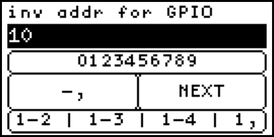
Inverter address
This menu is only visible if the “Both” option is selected. It allows the user to select the one or two inverter addresses controlled by the internal GPIO. The other addresses will be logically (from low to high) mapped to the external GPIO modules. For example, if 5 inverters are configured, 1,2,3,4,5 and only 2 external GPIO modules are configured and “Inverter address” is set to 3,4: The first GPIO modules is connected to inverter 1, the second GPIO module to inverter 2 and GPI1 is connected to inverter 3, GPI2 to 4. Inverter 5 has no arc detection connected. Setting the “Inverter address” to 1 in this situation connects inverter 1 to GPI1 and inverter 2 to external GPIO 1 and inverter 3 to external GPIO 2.
Connecting the external arc detection
When connecting the external arc detection please check the following items:
- Make sure the arc detection is not latched on detection.
- Make sure the GPIO of the SolarGatewaySE or input on the external GPIO are HIGH when no detection is done and LOW when a detection is done.
- Check the functionality of the external arc detection
- Check the functionality of the configured SolarGatewaySE, check if the correct inverter is turned-off when a detection is done.
GPIO control
Allows the user to add multiple rules for the onboard GPIO. Actions can be triggered depending on the GPI (General Purpose Input) state or states can trigger GPO (General Purpose Output). The SolarGatewaySE has two GPI and two GPO.
Each rule added to the list can only handle one state, for example the following setting: “IN1 is HIGH then set Min gen set to TRUE” Will limit the generation when input1 becomes HIGH. After input1 becomes LOW again, no new action is triggered, so the system will stay in Min gen. To return to normal operation when input1 is low again, the following rule should also be added: “IN1 is LOW then set Min gen set to FALSE”
Device settings
This part of the manual will describe all device settings and configurations.
ETH0 settings
Shows the actual status of the ETH0 port, and allows user to change port IP configuration.
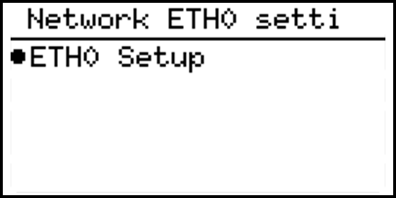
ETH0 Setup
ETH0 Type
Select the type of ETH0 connection, options are:
- DHCP
- STATIC

Note
When DHCP is selected as network type for ETH0, no other settings are needed for configuration. If Static is selected as ETH0 network type, other settings below are needed.
ETH0 IP Address
Enter the IP address of the ETH0 network, for example: “192.168.0.10”
ETH0 Gataway IP address
Enter the IP address of the network default gateway, for example: “192.168.0.1”.
This field can be left empty when there is no default gateway for this connection (and therefore no internet connection through this port).

ETH0 Netmask
Enter the network Netmask, for example: “255.255.255.0”.

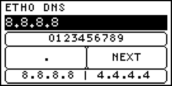
ETH0 DNS
Enter the DNS setting for ETH0, for example: “8.8.8.8”.
This field can be left empty when there is no DNS required.
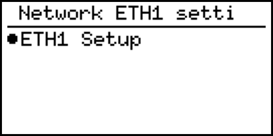
ETH1 settings
Shows the actual status of the ETH1 port, and allows user to change port IP configuration.
ETH1 Setup
ETH1 Type
Select the type of ETH1 connection, options are:
- DHCP
- STATIC
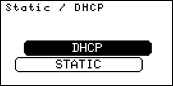
Note
When DHCP is selected as network type for ETH1, no other settings are needed for configuration. If Static is selected as ETH1 network type, other settings below are needed.
ETH1 IP Address
Enter the IP address of the ETH1 network, for example: “192.168.0.10”

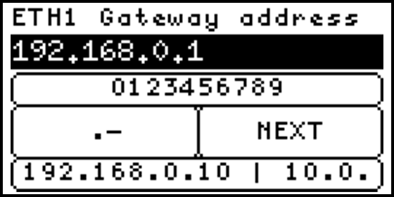
ETH1 Gataway IP address
Enter the IP address of the network default gateway, for example: “192.168.0.1”.
This field can be left empty when there is no default gateway for this connection (and therefore no internet connection through this port).
ETH1 Netmask
Enter the ETH1 Netmask, for example: “255.255.255.0”.
ETH1 DNS
Enter the DNS setting for ETH0, for example: “8.8.8.8”.
This field can be left empty when there is no DNS required.

Modbus settings
This explains the RTU setup for:
- RTU-A (X10)
- RTU-B (X11)
- RTU-C (X12)
RTU configuration
The following inputs are required to complete RTU configuration:
- Baudrate
- Parity
- Databits
- Stopbits
The default port configuration is 9600 8N1.
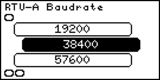
Baudrate
Select the baudrate for the RTU connector, options are:
- 9600
- 19200
- 38400
- 57600
- 115200
- 230400
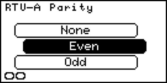
Parity
Select the parity for the RTU connector, options are:
- None
- Even
- Odd
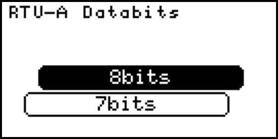
Databits
Select the databits for the RTU connector, options are:
- 8 bits
- 7 bits
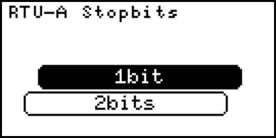
Stopbits
Select the stopbits for the RTU connector, options are:
- 1 bit
- 2 bits
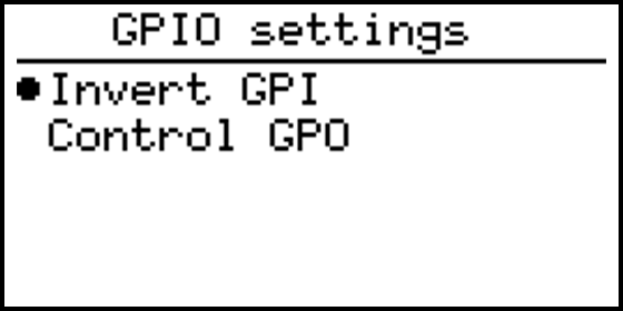
GPIO settings
The GPIO page shows the actual status of the input ports.
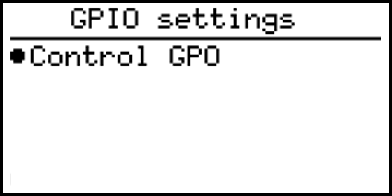
Control GPO
This menu allows the user to directly control the two output ports on te SolarGatewaySE.
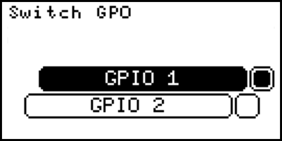
Warning
Forcing the GPO state can counteract the intended function!
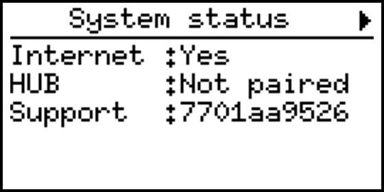
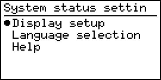
System settings
This page shows actual connection status of the SolarGatewaySE.
- Internet, yes if the device was able to ping to an external ip.
- HUB, paired if the user has already paired the device to the HUB.
- Support, shows the support ID when support is enabled.
System settings contains
- Display setup (Dim brightness and Contrast settings)
- Language selection
- Help
Display setup (Dim brightness)
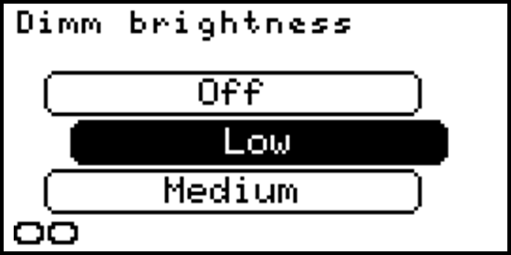
Select the low level of the backlight intensity. The SolarGatewaySE will reduce the backlight to the configured intensity when the buttons are not pressed for a while.
Display setup (Contrast settings)
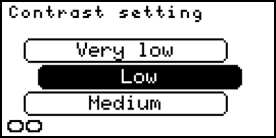
Configures the display’s contrast. By hovering over the options, the display contrast will change to the selected intensity.
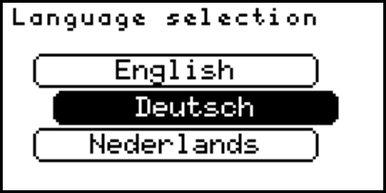
Language selection
Configures the system language for all status and configuration pages.
Help
Shows a qr code with a link to the online manual of the SolarGatewaySE. Use your phone to scan the qr code and open the manual.
Update settings
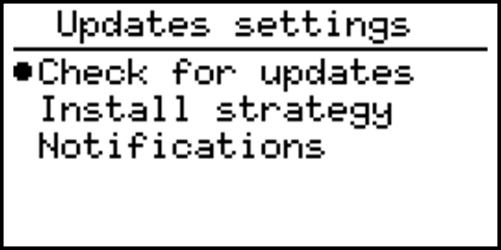
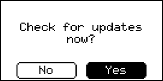
Check for updates
Manually verify if any software updates are available. The SolarGatewaySE should be connected to the internet to check for new updates.
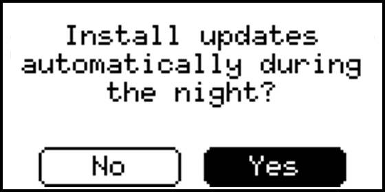
Install strategy
Selects the strategy to run updates. Two options are available:
- Automatically: SolarGatewaySE will automatically download and install available updates at night.
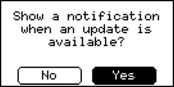
- Manual: If enabled a notification is shown when an update is available. The device will not automatically install updates.
Notifications
Turn on or turn off update notifications on the SolarGatewaySE.
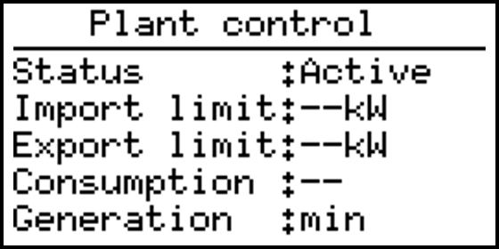
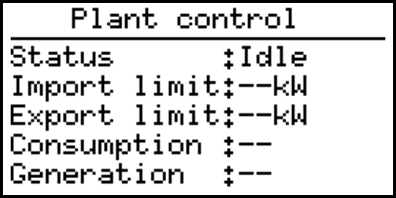
Plant control
This page shows the actual plant control status. When no plant control command is currently running the status is “idle” and all items contain “–”. When a plant control command is remotely given the status becomes “active” and the given command is shown at the right item.
When a plant control command is active the external LED turns blue.
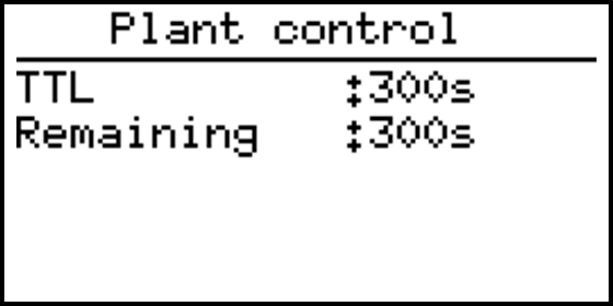
When no plant control is active the plant control page shows a idle status:
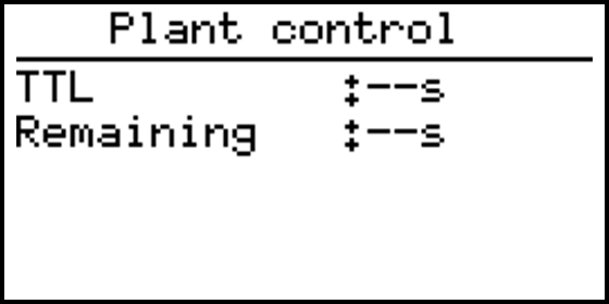
When plant control is active the plant control page shows active status with the current control value. In this example the control item is generation to min with a Valid time (TTL) of 300 seconds.